Bajdi electronics

Hobby electronics website

Browse: Page 21

Bajdupod 9G: it walks :)

By Bajdi on October 16, 2012

I have spent a lot of time on my little hexapod the last couple of days. I have finished writing the code for the basic walking gaits, forward/backward/left and right. This is the walking gait I have come up with:
FORWARD walking gait
knee up 1,3,5 knee down 2,4,6
hip forward 1,3,5 hip backward 2,4,6
knee down 1,3,5 knee up 2,4,6
hip backward 1,3,5 hip forward 2,4,6

BACKWARD walking gait
knee up 1,3,5 knee down 2,4,6
hip backward 1,3,5 hip forward 2,4,6
knee down 1,3,5 knee up 2,4,6
hip forward 1,3,5 hip backward 2,4,6

LEFT walking gait
knee up 1,3,5 knee down 2,4,6
hip backward 1,3,4,6 hip forward 2,5
knee down 1,3,5 knee up 2,4,6
hip forward 1,3,4,6 hip backward 2,5

RIGHT walking gait
knee up 1,3,5 knee down 2,4,6
hip forward 1,3,4,6 hip backward 2,5
knee down 1,3,5 knee up 2,4,6
hip forward 2,5 hip backward 1,3,4,6

Then I decided to try and remote control Bajdupod, I already have a remote control based on an Arduino Uno with joystick shield and nRF24L01 module which I have used with my Rover 5. So I needed to fit an nRF24L01 module to my hexapod. The 12 servos are connected to my Bajduino 3A which is based on the ATmega328P-PU, so 12 servos use 12 pins. I have used 1 analog pin to monitor the battery voltage. That doesn’t leave many pins free. I solved this by adding another of my PCB creations, the Bajduino 328RF24. The Bajduino 328RF24 is a small (5x5cm) board that has an ATmega328P-PU and a header for the nRF24L01 module. With the plan to let both micro controllers talk to each other over the I2C bus. There is one catch though, the Bajduino 328RF24 runs at 3.3V. To connect both micro controllers I used my logic level converter to convert the I2C signals to the right voltage. I didn’t have much trouble in writing the code for the nRF24L01 modules as I have used them before. But I spent quite a lot of time getting the I2C communication to work. As you can see in the video my code is still far from perfect.

While making the video I damaged another servo. I have had a bit of bad luck with my servos, I’ve destroyed quite a few the last week… This made me realise that these little micro 9G servos are not suited for my hexapod. The base is quite wide so there is a lot of strain on them. I’ve ordered some Towerpro MG90 servos, these have metal gears and should be a bit stronger. Hopefully my Bajduino 3A with LM2576 3A 5V regulator will be strong enough to power those servos. During the many test sessions I burnt my finger at the small heatsink I put on the regulator. To prevent it from melting or blowing up I added an old 60mm pc fan on top of it. It’s amazing what a little bit of air can do, the regulator gets barely hot now.

My next plans with Bajdupod 9G are to get my code in order. Replace all the servos with some stronger ones. Then I will add some sensors an try and write a autonomous sketch for it. I also have some 10mm RGB leds that I will glue to the chassis, it must have some eye candy 🙂
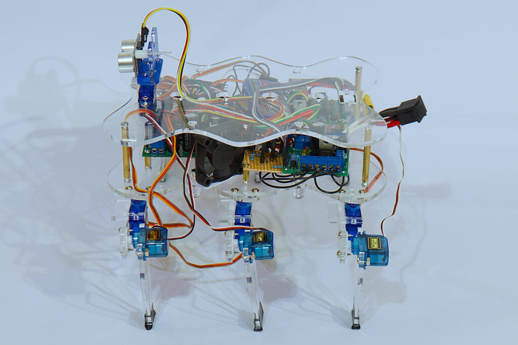
Hexapod
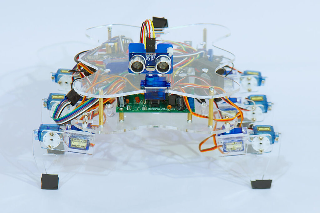
Hexapod
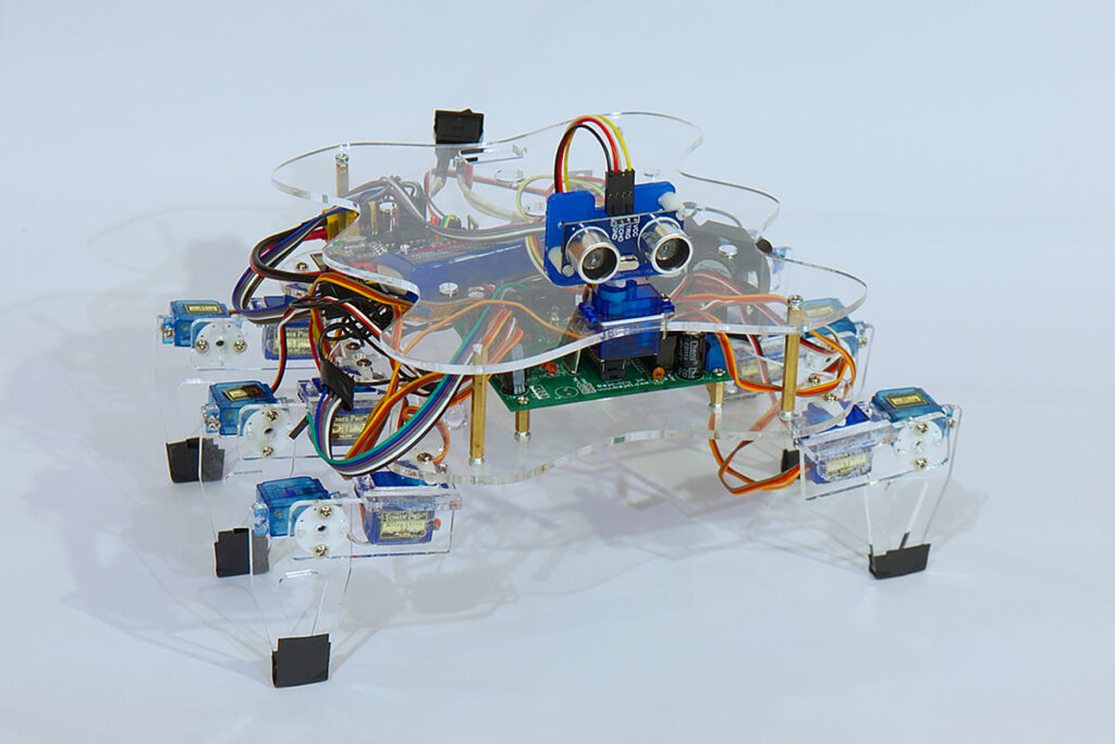
Hexapod
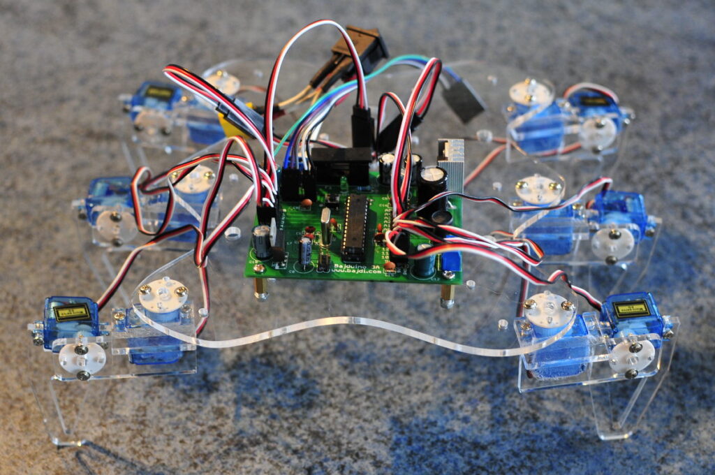
Hexapod

Hexapod

Hexapod

Posted in Bajdupod 9G | Tagged hexapod, nRF24L01, robot, servo | Leave a response

Building a hexapod: Bajdupod 9G

By Bajdi on October 7, 2012

Hexapod

Hexapod

When I started out with Arduino I stumbled on the letsmakerobots.com website. I found lots of robot projects on LMR, it’s amazing what people can make at home today. One particular kind of robots sparkled my interest, hexapods. Controlling and powering lots of servos looked quite difficult to me so I first started with my Rover 5 and later with a little line following robot. Now that I have a bit more experience building robots it was time to built my own hexapod, the Bajdupod 9G.
An ATmega328P-PU with the Arduino servo library can control a maximum of 12 servos. I wanted to keep things simple for my first hexapod and chose to use 2 DOF legs. So I can use an ATmega328 to control the 12 servos. I designed the base and legs in Autocad and had the parts laser cut in acrylic by a local company. I then bolted and glued the different parts and servos together. This didn’t go according to my plan. I had bought a dozen micro 9G servos on Ebay and first used these. But I had a lot of trouble connecting them to the servo horns. These small servos come with tiny screws to bolt the servo horn to the servo. The little screws kept breaking. Leaving me with unusable servos because a small piece of the screw was stuck in the servo. I then tried to glue the servo horns to the servos but the legs kept falling of. I nearly gave up until I remembered I had some other small servos, SG90 servos. They are about the same size then the 9G servos. So I replaced the 6 hip servos with SG90’s, these come with better screws. After hours of swearing I finally had a hexapod that didn’t fell apart.
To control the servos I use my Bajduino 3A board. I has an ATmega328P-PU with Arduino bootloader and a 3A 5V switch-mode voltage regulator.
After connecting all the servos to the Bajduino 3A I tested all the servos and put all the center, minimum and maximum values in a spreadsheet. Then I wrote a sketch to let the hexapod walk forward. After some minor tweaking I now have a hexapod that can walk forward 🙂

Posted in Bajdupod 9G | Tagged Bajduino, hexapod, robot, servo, SG90 | 6 Responses

Serial communication with the EasyTransfer library

By Bajdi on October 6, 2012

Arduino serial communication

Arduino serial communication

While I was searching for information on how to establish communication between 2 Arduino’s over the I2C bus I stumbled on Bill Porters website. He has written an Arduino library for easy serial communication between 2 Arduino’s. And someone else has made a version of the same library for easy I2C communication.

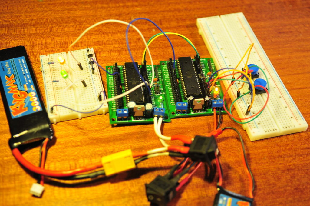
The EasyTransfer serial library has 2 versions, one for hardware serial and one for software serial. The libraries can be found on github. Today I tried out the EasyTranfer library and used it with the hardware serial ports of 2 ATmega1284’s. The ATmega1284 has 2 serial ports so while you can use one serial port for the serial monitor you can use the other serial port for communication with another micro controller.

I connected 2 push buttons to one ATmega1284 and 2 leds to the other ATmega. For serial communication you must connect RX to TX and TX to RX. Both micro controllers must also share the same ground. In the following sketches the state of the push button is sent to the other micro controller over the serial connection. I used the bounce library to debounce the push buttons. The EasyTransfer library is indeed easy to use for simple serial communication 🙂 I only tried one way communication but the library allows communication in both directions.

The transmitter (TX) sketch:

// http://www.bajdi.com
// TX serial communication with the EasyTransfer library
// This sketch sends the state of the 2 push buttons using serial 2
// The sketch will only work with an Arduino Mega unless you change the serial2 to serial

#include <EasyTransfer.h>
#include <Bounce.h>
//create object
EasyTransfer ET; 

struct SEND_DATA_STRUCTURE{
  //put your variable definitions here for the data you want to send
  //THIS MUST BE EXACTLY THE SAME ON THE OTHER ARDUINO
  int led1State;
  int led2State;
};

const int button1 = 0;    // the number of the first pushbutton pin
const int button2 = 1;    // the number of the first pushbutton pin

int lastButton1State = LOW;   // the previous reading from the first push button pin
int lastButton2State = LOW;   // the previous reading from the second push button pin

Bounce bouncer1 = Bounce(button1,50);   //setting up the debouncing for the first push button
Bounce bouncer2 = Bounce(button2,50);   //setting up the debouncing for the second push button

//give a name to the group of data
SEND_DATA_STRUCTURE mydata;

void setup(){
  Serial1.begin(115200);
  pinMode(button1, INPUT);
  pinMode(button2, INPUT);
  
  //start the library, pass in the data details and the name of the serial port. Can be Serial, Serial1, Serial2, etc.
  ET.begin(details(mydata), &Serial1);
  
}

void loop(){
  
  bouncer1.update ( );    // Update the debouncer for the first push button
  bouncer2.update ( );    // Update the debouncer for the second push button
  
 int reading1 = bouncer1.read();     // Get the update value      
 int reading2 = bouncer2.read();     // Get the update value
 
  reading1 == HIGH;    
  reading2 == HIGH;
  
    if (lastButton1State == LOW && reading1 == HIGH) 
    {
    if (mydata.led1State == HIGH) {mydata.led1State = LOW;} 
    else {mydata.led1State = HIGH;}
    }
    lastButton1State = reading1;

    if (lastButton2State == LOW && reading2 == HIGH) 
    {
    if (mydata.led2State == HIGH) {mydata.led2State = LOW;} 
    else {mydata.led2State = HIGH;}
    }
    lastButton2State = reading2;
  
  ET.sendData();
  
  delay(150);
}

The receiver (RX) sketch:

// http://www.bajdi.com
// RX serial communication with the EasyTransfer library
// This sketch receives the state of 2 push buttons using serial 2 and lights up 2 leds
// The sketch will only work with an Arduino Mega unless you change the serial2 to serial

#include <EasyTransfer.h>

//create object
EasyTransfer ET; 

const int led1 =  3;      // the number of the LED1 pin
const int led2 =  4;      // the number of the LED2 pin


struct RECEIVE_DATA_STRUCTURE{
  //put your variable definitions here for the data you want to receive
  //THIS MUST BE EXACTLY THE SAME ON THE OTHER ARDUINO
  int led1State;
  int led2State;
};

//give a name to the group of data
RECEIVE_DATA_STRUCTURE mydata;

void setup(){
  Serial1.begin(115200);
  //start the library, pass in the data details and the name of the serial port. Can be Serial, Serial1, Serial2, etc. 
  ET.begin(details(mydata), &Serial1);

  pinMode(led1, OUTPUT);
  pinMode(led2, OUTPUT);

}

void loop(){
  //check and see if a data packet has come in. 
  if(ET.receiveData()){
    //this is how you access the variables. [name of the group].[variable name]
    //since we have data, we will blink it out. 
    if (mydata.led1State == HIGH)
    {
      digitalWrite(led1, HIGH);
    }
    else
    {
      digitalWrite(led1, LOW);
    }


    if (mydata.led2State == HIGH)
    {
      digitalWrite(led2, HIGH);
    }
    else
    {
      digitalWrite(led2, LOW);
    }


  }
  //you should make this delay shorter then your transmit delay or else messages could be lost
  delay(50);
 
}

Posted in Arduino sketches | Tagged ATmega1284, Serial | Leave a response

« PreviousNext »

Recent Posts

  • 3D Printer extruders
  • Mearm forked
  • Arduino time lapse – camera pan device
  • Bought a 199$* Prusa I3 3D printer
  • Simple DIY lab power supply
  • Bajduino
    • Bajduino 1284
    • Bajduino 328
  • Stepper robot arm

Recent Comments

  1. 200+ Arduino Projects List For Final Year Students - He Loves Math on Obstacle avoiding robot made from cheap parts
  2. MP3 Alarm Clock: Crafting Customized wake-Up tunes with Arduino on Arduino MP3 alarm clock
  3. Bas on L9110 H-bridge module
  4. Victor on L9110 H-bridge module
  5. WAQAR AHMED on Dimming led with IR remote control

Archives

  • June 2016
  • August 2015
  • May 2015
  • January 2015
  • December 2014
  • November 2014
  • May 2014
  • April 2014
  • March 2014
  • February 2014
  • January 2014
  • December 2013
  • November 2013
  • October 2013
  • September 2013
  • June 2013
  • May 2013
  • April 2013
  • March 2013
  • February 2013
  • January 2013
  • December 2012
  • November 2012
  • October 2012
  • September 2012
  • August 2012
  • July 2012
  • June 2012
  • May 2012
  • April 2012
  • March 2012
  • February 2012
  • January 2012
  • December 2011

Categories

  • 3D printing
  • Arduino
  • Arduino sketches
  • Bajdupod 996R
  • Bajdupod 9G
  • Bob the biped
  • Buying parts
  • Dagu Rover 5
  • Dagu service droid
  • Gentoo
  • Insectbot
  • Line following robot
  • Raspberry Pi
  • Self balancing bot
  • Bajduino
    • Bajduino 1284
    • Bajduino 328
  • Stepper robot arm

Copyright © 2026 Bajdi electronics.

Powered by WordPress and Hybrid by Bajdi.