By Bajdi on September 30, 2012
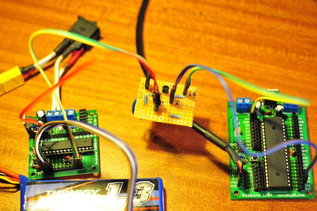
I have been playing with my self built Arduino’s the last weeks. One of my designs is a small (5x5cm) board with an ATmega328P-PU and a header for a nRF24L01 wireless module. I named it the Bajduino 328RF24 🙂
Since the nRF24L01 modules work at 3,3V I decided to let the ATmega run @ 3,3V. I used a 16MHz resonator, this is just out of spec according to the Atmel datasheet but it seems to work. I designed the board to use in a robot, the board just needs to do the wireless communication. It must then sent the data it receives over the I2C bus to another Arduino fitted to the robot. The other Arduino runs at 5V, this causes a small problem. You can not connect 3V3 and 5V I2C signals together. You must use a logic level converter to change the signal to the correct voltage. I2C is bidirectional so it must work both ways, the 3V3 signals must be converted to 5V and the 5V signals to 3V3. The easy way to solve this is to buy this board from Sparkfun. It even costs less then 2$, unfortunately I live in the EU and the shipping would cost a lot more then the board itself. I also found it at a German web shop that sells Sparkfun stuff but the shipping alone was 9€.
So I decided to heat up my solder iron and make it my self. I2C is an invention of Philips, they originally came up with it to connect various sensors in VCR’s. I2C only uses 2 pins, SDA and SCL. These are pin A4 and A5 on an Arduino Duemilanove/Uno, you also have to connect the grounds of the 2 Arduinos together. Philips have published an application note (n°97055) for a bi-directional level shifter for the I2C-bus and other systems. You can download it here. On page 10 there is an example schematic for a 3V3 – 5V bidirectional level shifter. You only need 4 resistors and 2 small logic level mosfets to make it work.
I made a schematic and board in Eagle and then soldered the components to a small piece of perfboard. I used 2N7000 mosfets as I had a dozen of these lying around, for the resistors I chose a value of 2K2. I added a couple of male pins to connect it to my Bajduinos. I then put the example sketches of the wire library in the 2 Bajduinos to test the my logic level converter and it works 🙂
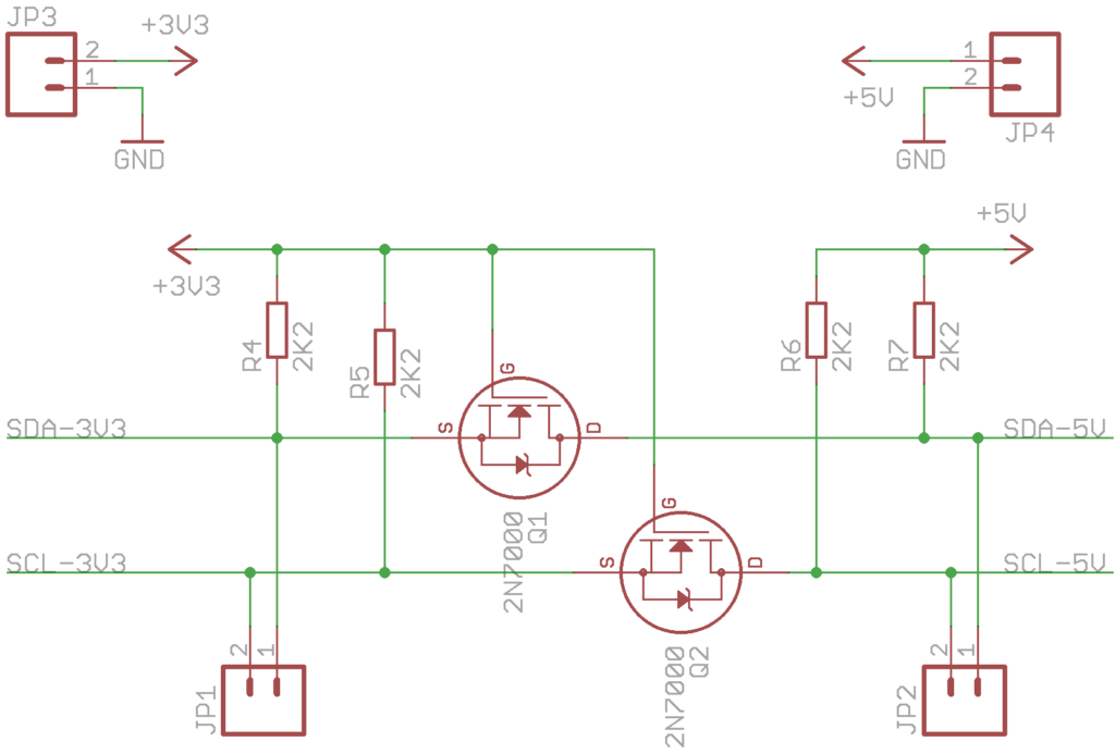
Logic level converter schematic
Posted in Arduino | Tagged I2C |
By Bajdi on September 7, 2012
A couple of months ago I started playing with Eagle. Something I had always wanted to try but never had the time or courage to get started. After playing with Arduino’s and a Dagu Red Back Spider I had the idea to design a board with the ATmega328P-PU and a powerful 3A 5V switchmode regulator. That way I could easily attach a lot of servos to the board and not need to worry about how to power them.
I chose the LM2576 regulator because of its price, only 0,58$ @ Tayda electronics. It took me quite some time to learn Eagle and design what I wanted. I changed the design a dozen times, retraced the board a couple of times. But now I can say it was worth it. As you can see in the video the board can power 12 small micro 9G servos without trouble. The 5V line stays pretty stable. I was worried that the servos might cause the ATmega to reset, for that reason I put a lot of capacitors on the board. I don’t know if they really make a difference, but I had a lot of capacitors in my parts box so I might as well use them.
There is also a 3,3V low dropout voltage regulator on the board to power 3,3V devices. I also put a fuse on the board, I did not put it on the board to protect the ATmega. It has more to do with the fact that I will use a Lipo battery to power the board in my next robot. I’ve started designing a small hexapod with 2 DOF legs. The hexapod will use 12 micro 9G servos. So now that I have the electronics figured out it’s time to get the mechanical design ready.
Posted in Arduino | Tagged ATmega328P-PU, Bajduino |
By Bajdi on September 2, 2012
Some time ago I bought a cheap 9DOF board on Ebay. The board has 3 sensors, an ADXL345 accelerometer, HMC5883L magnetometer and an ITG3200 gyroscope. All 3 sensors are of the digital kind and use the I2C bus to communicate. These sensors need a voltage of 3,3V to work, luckily the board has an onboard voltage regulator and level converter that converts the 5V I2C signals from my micro controller to 3,3V. So I could just hook it up with 4 wires to my Dagu Red Back Spider robor controller.
These 3 sensors are quite advanced with lots of features. These are all explained in their extensive datasheets. My programming skills are not up to the task of programming them on my own. Thankfully some smart people have written a nice library for these things so that I can do something useful with my little board. I found a nice tilt compensated compass sketch and libraries for the ADXL345 and HMC5883L sensor at the Love electronics website. This sketch takes calculates the heading from the magnetometer and applies tilt compensation. The tilt is measured from the accelerometer.
I integrated the sketch in to my existing sketch and sent the heading that is calculated from the reading of the 2 sensors to my remote control. That way I can see the heading on my LCD, 2 values are shown. The HNC value is the heading without the compensation by the accelerometer and the HC value is the compensated heading.
Posted in Dagu Rover 5 | Tagged ADXL345, HMC5883L, I2C, robot |