Bajdi electronics

Hobby electronics website

Browse: Page 6

DFrobot insectbot

By Bajdi on January 25, 2014

DFrobot insectbot

DFrobot insectbot

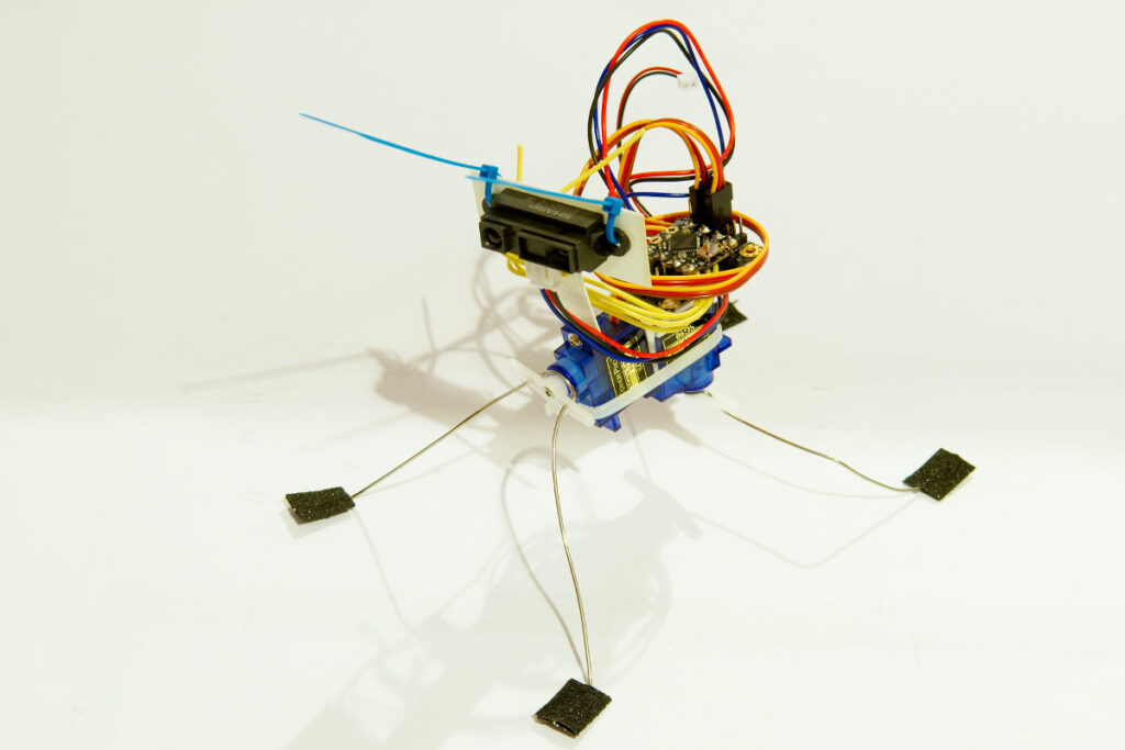
DFrobot sent me their latest robot kit, the insectbot kit. It’s a small 2 servo robot that’s easy to built and program. The kit is ideal for people who want to built their first robot. It comes with an Arduino compatible micro controller. The insectbot kit is sold for less then 30$, so it doesn’t require a big investment. And to my surprise that even includes the small Lipo battery and charger.

The package arrived from China in a rather big box:
DFrobot insectbot

DFrobot insectbot

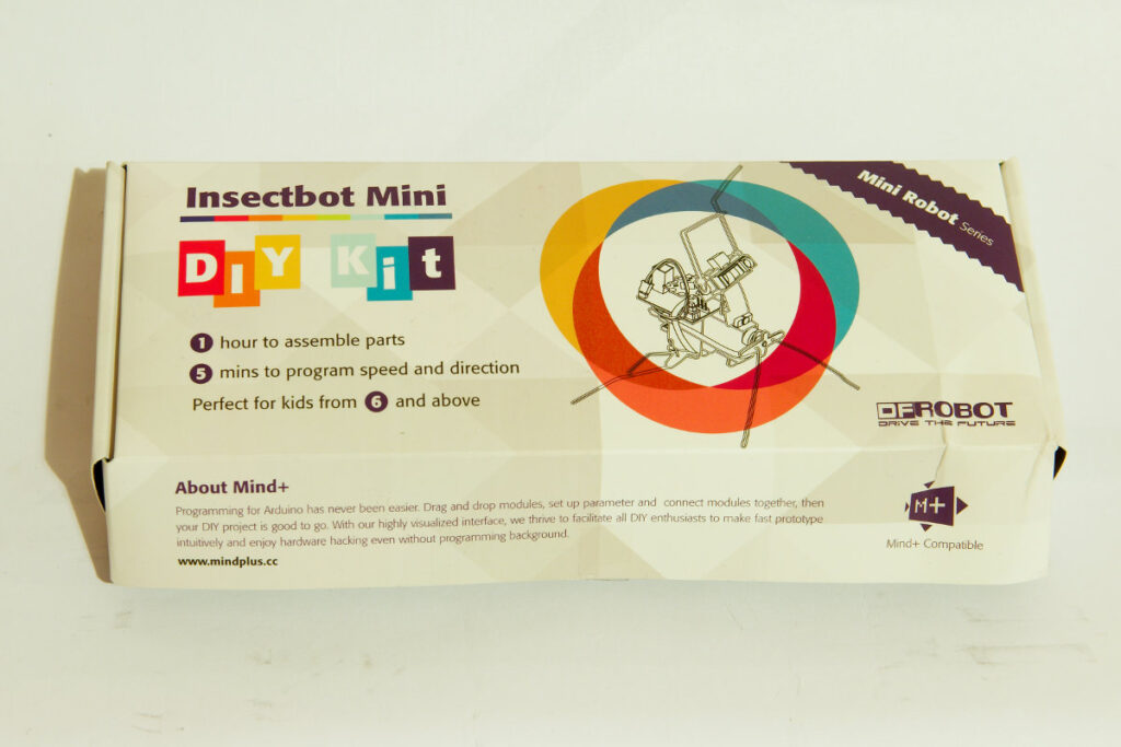
Inside the big box I found a small box containing all the parts to built the insectbot 🙂
DFrobot insectbot

DFrobot insectbot

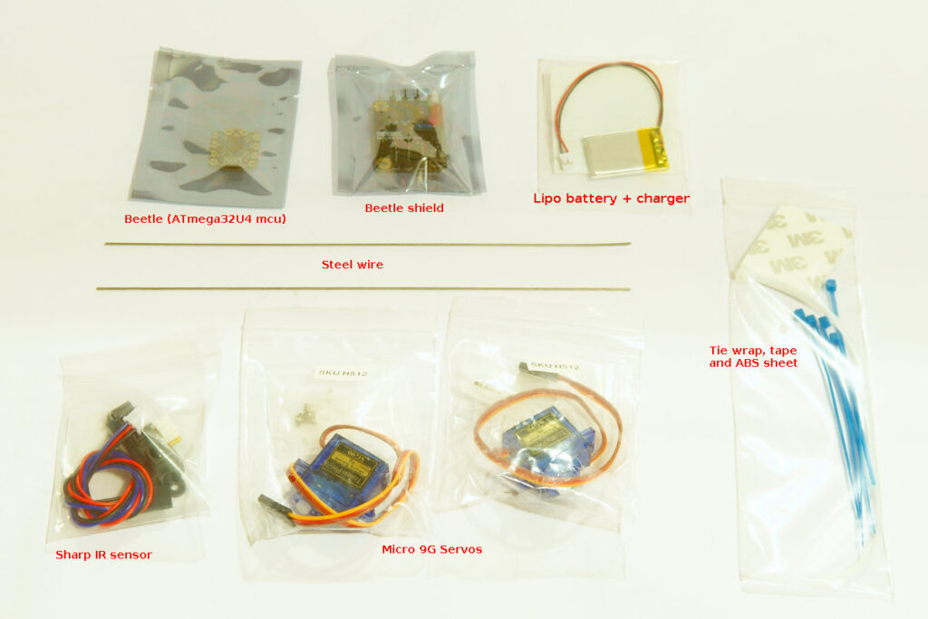
These are the parts of the insectbot:
DFrobot insectbot

DFrobot insectbot

  • 1x Beetle (Arduino compatible)
  • 1x Beetle Shield 2x 9g Micro Servo
  • 1x Sharp IR Sensor
  • 1x LiPo Battery 3.7V/ 180mAh + Charger
  • 2x Steel Wire 200mm x 1 mm
  • 1x ABS Sheet (50x50mm)
  • 1x Double Sided Foam Tape(L/W/H:40x30x3mm)
  • 5x Cable Tie 1.8x100mm
  • 1x Cable Tie 4x200mm

The kit does not include a manual or built instructions. But the creator of the robot kit has put built instructions on Instructables and there is a nice youtube video showing the building of an insectbot, watch it here. Making the kit does not take long, you can easily built it in less then an hour. To built the kit I used the following tools:

  • Scissors
  • Pliers
  • Cutting knife
  • Solder iron
  • Small screwdriver

Building the kit:

The chassis of the insectbot is made out of the bodies of the 2 servos and the Lipo battery. The parts are held together with double sided tape. Use a pair of scissors to cut up the double sided tape.
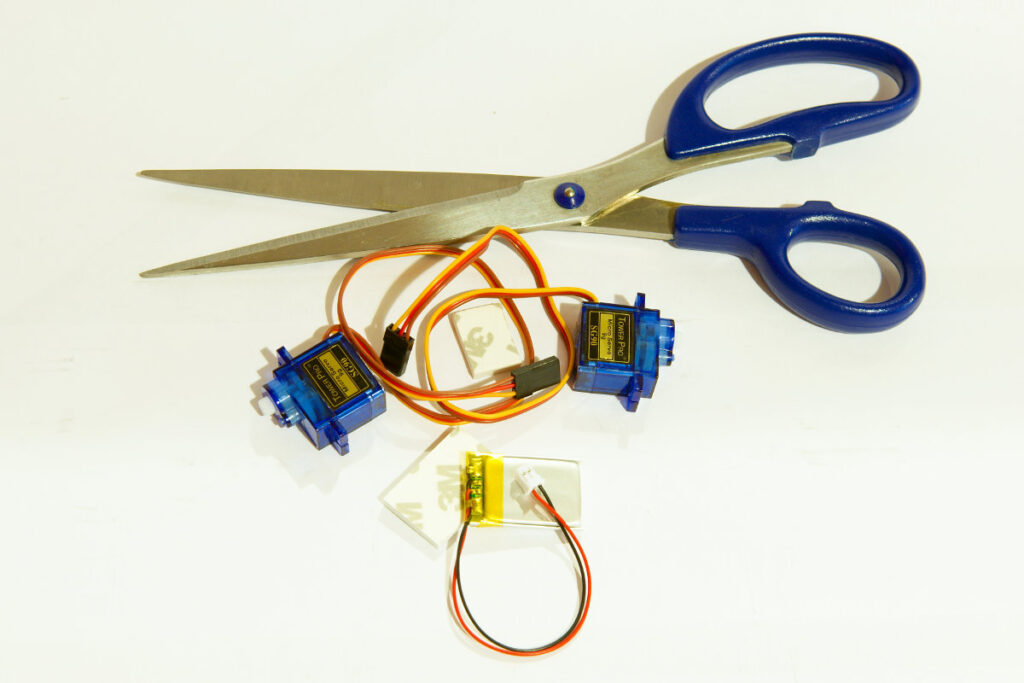
DFrobot insectbot

DFrobot insectbot

Then you need to join the 2 servos together using a piece of double sided tape and a zip tie:
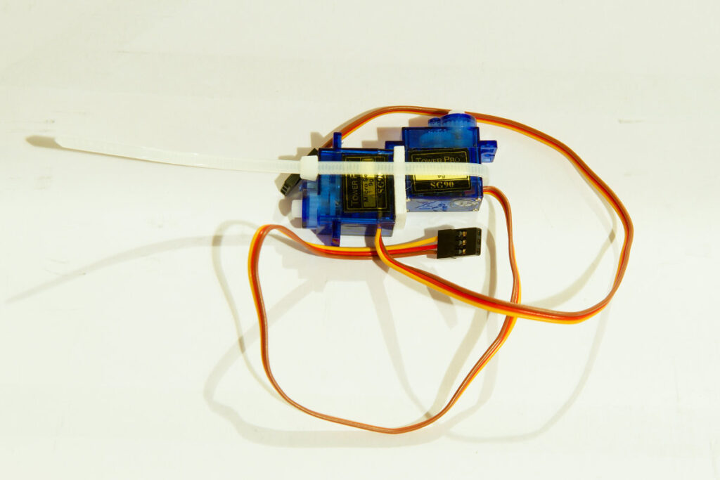
DFrobot insectbot

DFrobot insectbot

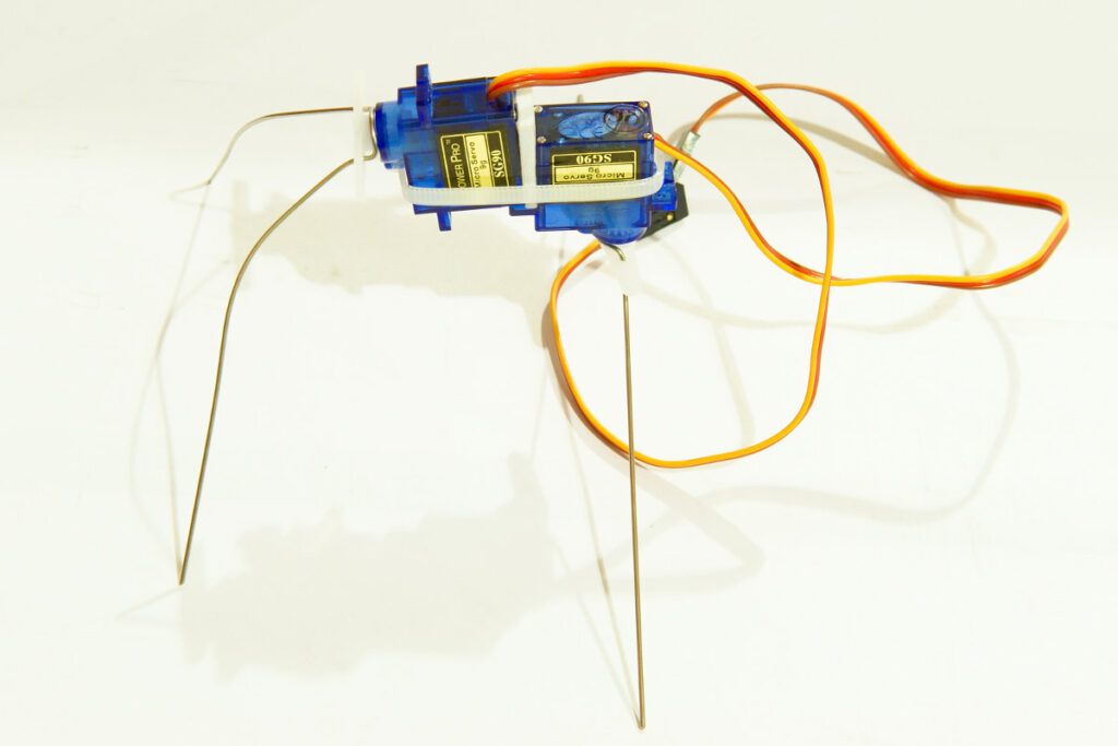
Now comes the hard part… Making the legs. You need to bent the steel wires so they can be used as legs. You need to bent them so they fit the servos. I bent them around a pen:
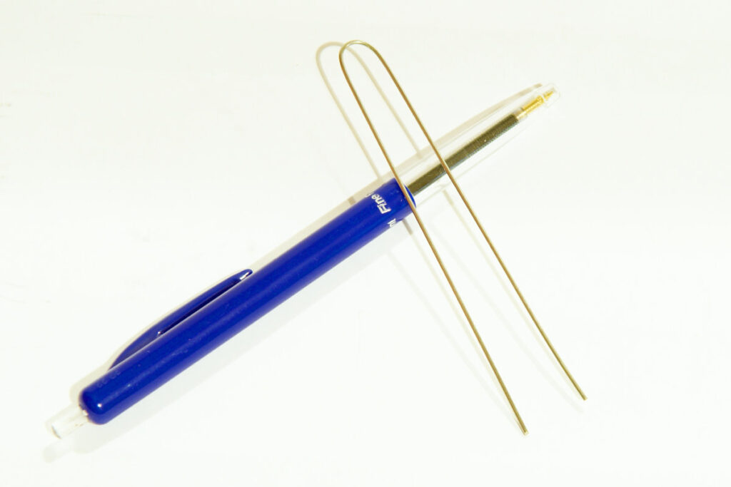
DFrobot insectbot

DFrobot insectbot

You then need to use pliers to bent a lip so they fit the servos. The wires go through the servos horn. Here is the result:
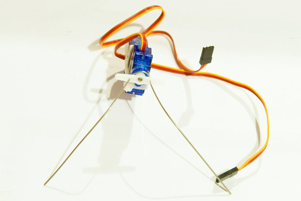
DFrobot insectbot

DFrobot insectbot

You need to do that for both wires. The end result does not matter much at this point. When the robot is finished you will probably adjust them further to optimize the walking gait.
DFrobot insectbot

DFrobot insectbot

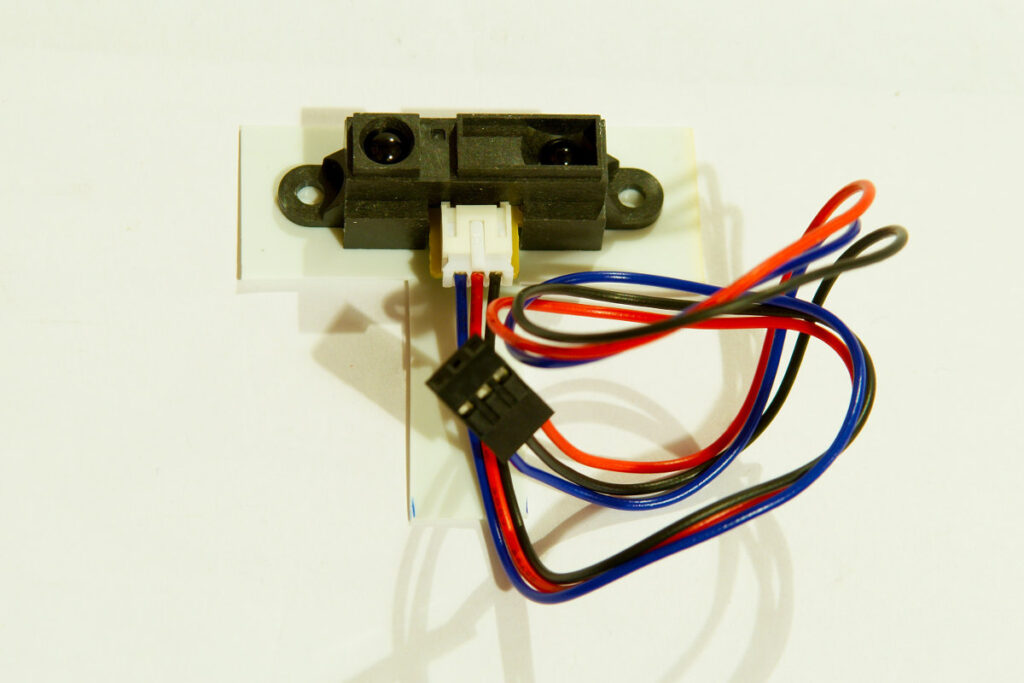
Next step is fitting the Sharp IR sensor to the small piece of ABS sheet. Using a pair of scissors you need to cut it so the bottom is the same width of the servo and the top is big enough for the IR sensor.
DFrobot insectbot

DFrobot insectbot

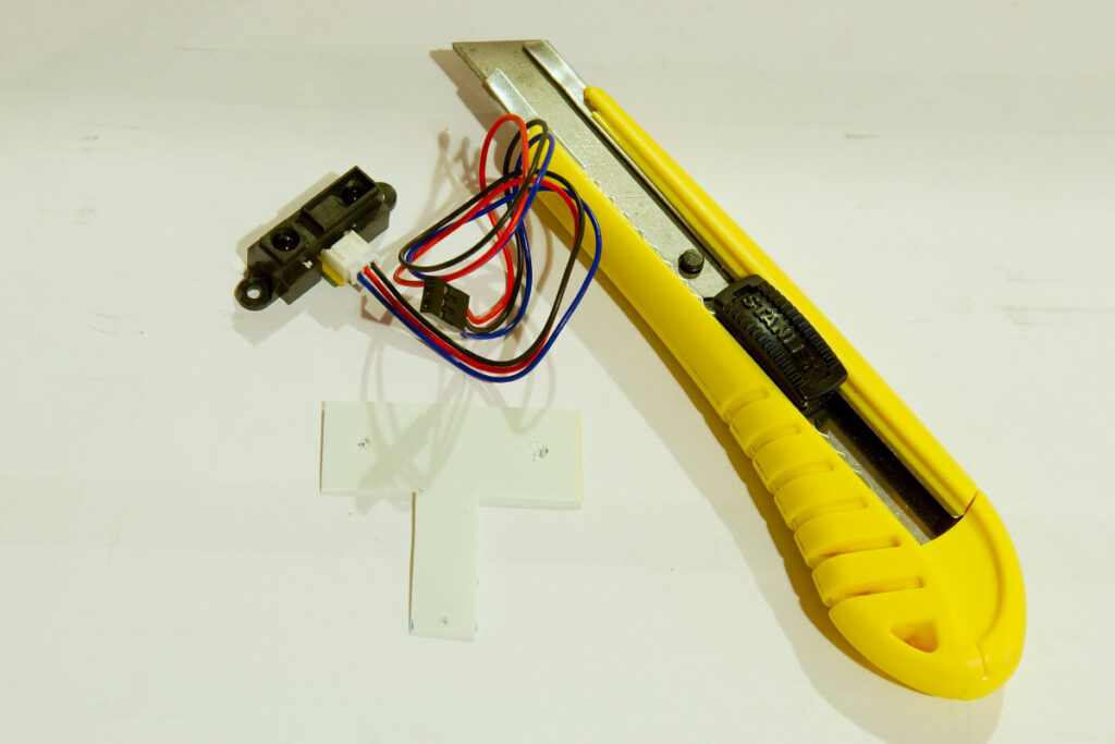
You have to fit the botton of the ABS sheet to the front servo using the screws supplied with the servo. I first made a hole in the ABS to easily attach it with the screw. The IR sensor is attached by making 2 holes in the ABS sheet and using 2 zip ties. I used the tip of a cutting knife to make the small hole to attach it to the servo and 2 bigger holes to fit the IR sensor.
DFrobot insectbot

DFrobot insectbot

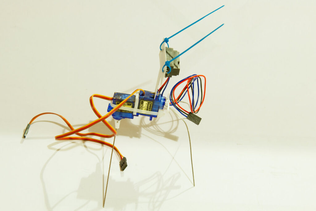
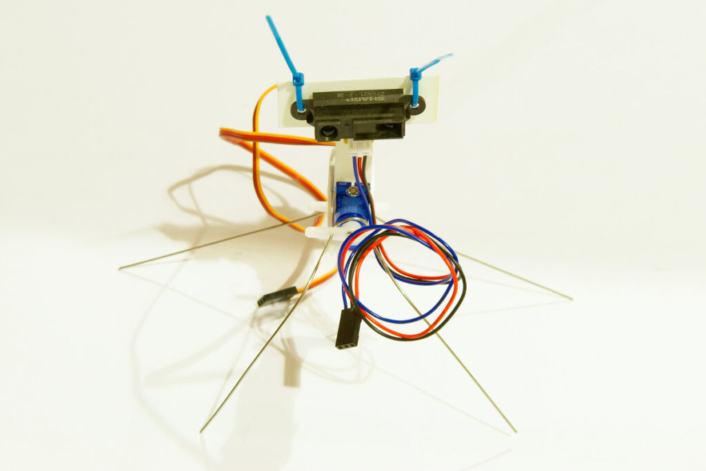
Then you need to zip tie the IR sensor to the ABS sheet and screw the assembly to the front servo. You should then have something like this:
DFrobot insectbot
DFrobot insectbot

DFrobot insectbot

DFrobot insectbot

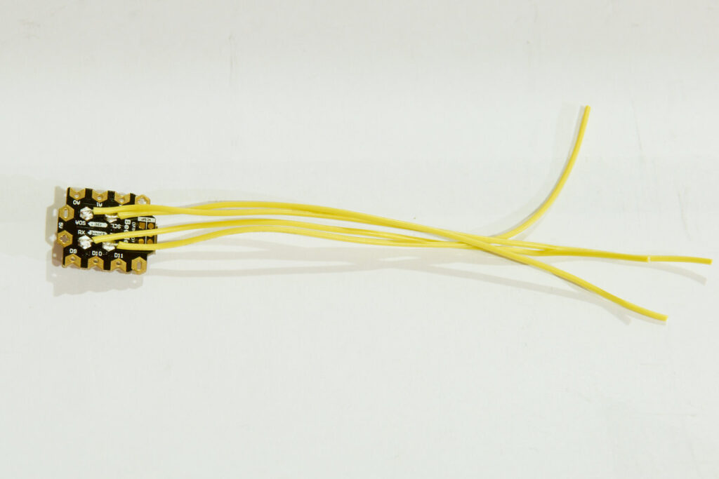
Then it’s time for some soldering. The Beetle has to be soldered to the Beetle shield. The Beetle also has some pads on the bottom of the board. If you want to use them you must solder some wires to these pads. Once the Beetle is soldered to the shield they are not accessible any more. So I first soldered some wires to the bottom pads of the beetle. This is quite easy since the pads are pretty big.
DFrobot insectbot

DFrobot insectbot

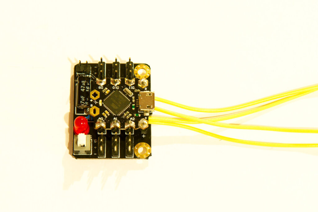
Then you need to solder the Beetle to the shield:
DFrobot insectbot

DFrobot insectbot

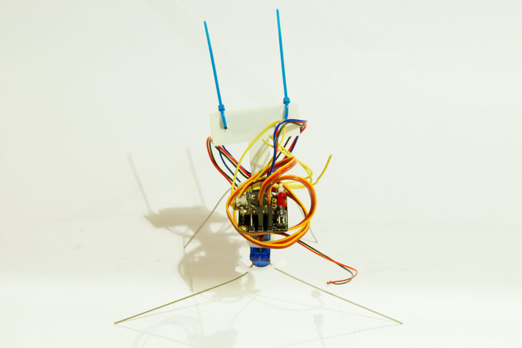
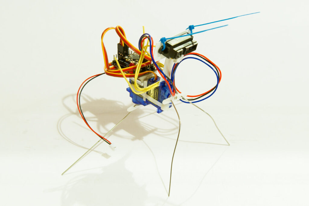
The beetle shield fits on top of the Lipo battery. You join them by using a piece of double sided tape. The battery and beetle shield then fit on the back servo. Like this:
DFrobot insectbot
DFrobot insectbot

DFrobot insectbot

DFrobot insectbot

The beetle shield makes it very easy to connect the servos and IR sensor. You can just plug them on the shield. I used pin D9 and D10 for the servos and A0 for the IR sensor. The Sharp IR sensor does not need any special code, it is just an analog sensor. The servos can be controlled by the Arduino servo library that comes with the Arduino IDE.

The Beetle board or shield don’t have a voltage regulator so you can’t use a battery that gives more then 5V. Luckily the insectbot kit comes with a small single cell Lipo battery. It also comes with a small Lipo charger. The Beetle shield has 2 male pins to connect a battery. Unfortunately the plug of the battery doesn’t fit the pins very well. I bent the pins a bit to make them fit better.

Programming the Beetle is not difficult. It uses the same micro controller as the Arduino Leonardo, the ATmega32U4. The beetle has a micro USB plug to connect it to your computer. You can download the Insectbot code on the DFrobot website. Just open the sketch in the Arduino IDE, select Arduino Leonardo as board and click upload.

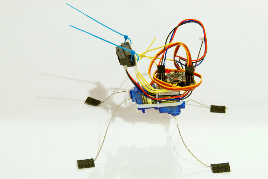
Making the insectbot walk with the above code is not that easy as expected from a 2 servo walker. So I started fine tuning my little insectbot. I bent the legs so the robot has a lower point of gravity. I also fitted some antislip tape to the legs. I’ll be honest it still doesn’t walk very fast, it’s more a wiggling robot then a walking robot. But that is the nature of the design.
DFrobot insectbot
DFrobot insectbot

Posted in Insectbot | Tagged robot | 1 Response

Dagu service droid: the start

By Bajdi on January 19, 2014

Dagu service droid

Dagu service droid

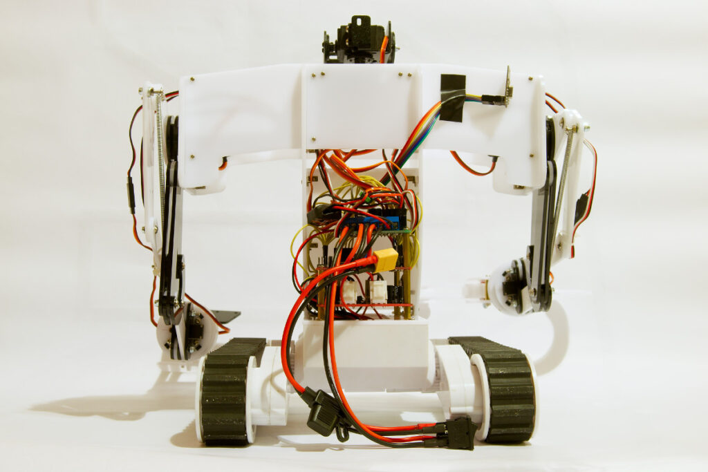
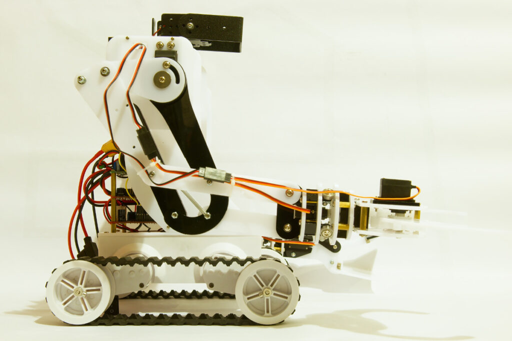
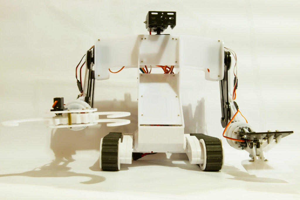
When I saw the offer on letsmakerobots.com to buy a new robot kit from Dagu at a special price I didn’t hesitate… Dagu’s new robot kit is the “service droid”. It’s a kit that can be mounted on the popular Rover 5 platform. The service droid is made from hundreds of laser cut acrylic parts. All the parts are bolted together. You can download the manual here. It took me around 10 hours to put all the parts together and setup the servos. The kit has 2 robotic arms, each arm has 3 servos. On top of the torso there is pan/tilt kit using another 2 servos. This is a big kit containing lots of small parts, screws, … it’s not some toy that you can quickly put together. Since I got an early version I was quite surprised that all the parts fitted. It took me so long to put together because of the many parts and I had to redo some things that weren’t explained very well in the manual. The manual has since been updated making it easier to built.

Dagu service droid

Dagu service droid

When I ordered the Service droid I also ordered a new Rover 5 chassis. So I now have 2 Rover 5’s. I’ve actually moved all the parts from my old Rover 5 to the new chassis. The new version of the Rover has a new style of wheels and different encoders. I wanted to try the encoders with my mecanum wheels. So I used the new wheels and tracks on my old chassis. And used that as the platform for my service droid.

All the servos are included in the service droid kit, but it does not come with a micro controller or other electronics. So you are free to use your favourite micro controller. I chose the Dagu red back spider robot controller, it’s based on the ATmega2560 micro controller and has an Arduino bootloader. That gives me a massive amount of I/O to connect lots of sensors. I also bought the Dagu 4 channel motor controller to power the motors.

Dagu service droid

Dagu service droid

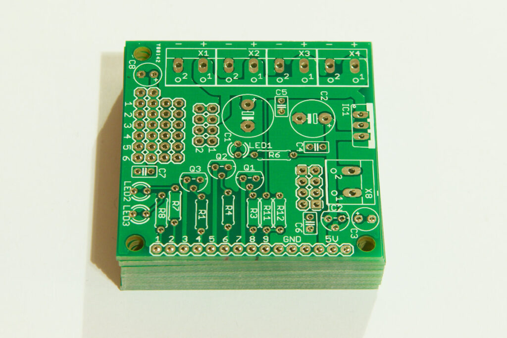
I’m using a 2S Lipo battery to power the motors and servos. To distribute the power to the motor controller, red back spider and UBEC (powers the servos) I designed a small PCB. This PCB has a voltage divider to monitor the battery voltage. There are 2 voltage regulators, a 5V (LM2940) voltage regulator for the logic of the motor controller and a small LP2950-3.3 regulator for 3.3V devices. The PCB also has a couple of leds which are handy for debugging and I also added a couple of transistors which may be useful in the future. Most importantly the board has a bunch of male pins that allow me to power the 8 servos of the service droid. 2 servos are powered straight from the Lipo battery. These are the servos that move the arms up and down. The other 6 servos are powered from a 5A UBEC.

Service droid power pcb

Service droid power pcb

After building the kit I took my remote control sketch for my old Rover 5 and modified it for the service droid. This lets me control the service droid with my self built remote control using a pair of 2.4GHz nRF24L01 modules. I made the following video:

After showing the video on Letsmakerobots the designer of the kit told me that the arms weren’t functioning correctly. I should have taken a better look at the manual. I have since corrected my mistakes 🙂

It’s not my intention to control the service droid with the nRF24L01 modules. I just used them to test all the functions of the robot. The next step is to add a Raspberry pi and camera. And try to control it over wifi. When I have that figured out I would like to try some autonomous things using OpenCV.

Posted in Dagu service droid | Tagged nRF24L01, robot | 2 Responses

Pololu Wixel and Arduino

By Bajdi on January 6, 2014

Pololu wixel

Pololu wixel

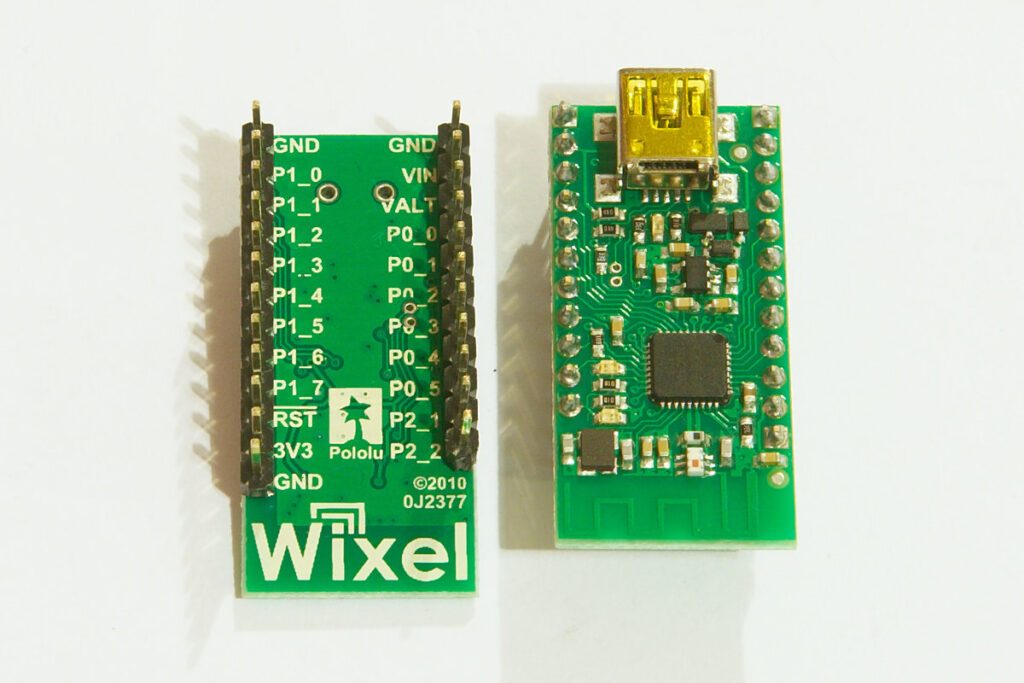
I’ve bought me a pair of Pololu Wixels during the black Friday sale last month. The Wixel is based on the CC2511F32 micro controller from Texas Instruments. It has an integrated USB controller and 2.4GHz RF transceiver. The micro controller is based on Intels old 8051 architecture.
I did not buy it to try and program an 8051 arch micro controller, I’m sticking to Arduino 🙂 The reason I bought these modules is that Pololu has made some nice software and scripts for them. I especially bought them because it is possible to upload Arduino sketches over a wireless link with a pair of Wixel modules. You can also use the Arduino serial monitor over the wireless link. Which is very handy when you are debugging a robot that is driving around.
Pololu has written an extensive user guide for the Wixel modules, you can find it here. I wanted to connect the Wixel module to one of my own Bajduinos to try them out. I started by installing the Pololu Wixel configuration utility. I did not have to install any modules or drivers on my GNU/Linux workstation. The Wixel configuration utility allows you to upload software to the Wixel module over USB. I installed the wireless-serial-v1.3 script to both modules. This script turns the Wixel modules in a wireless serial link. I needed to change one setting to make them work with my ATmega1284 based Bajduino. The default baud rate is set at 9600, I changed this to 115200 as I’m using an optiboot bootloader on my ATmega1284 boards.

Pololu wixel with arduino

Pololu wixel with arduino

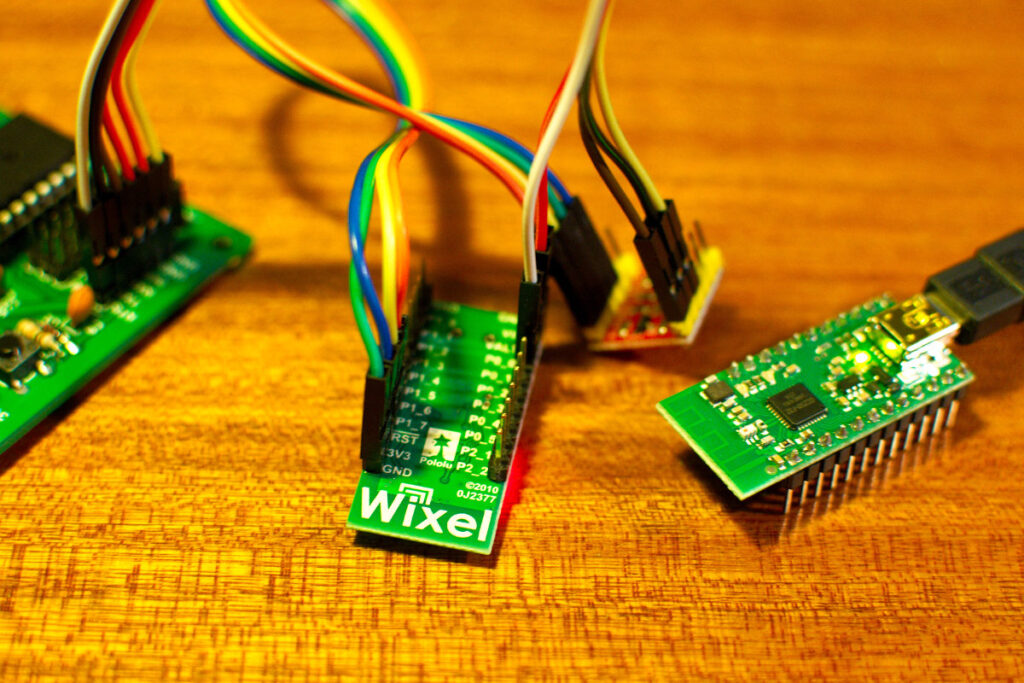
After uploading the wireless serial program I connected the Wixel to my computer over USB. It showed up in the Arduino IDE as a new serial device.
I then connected the other Wixel to my Bajduino. I had to go through the Wixel user guide a couple of times to find the right connections. The Wixel is a 3V3 device so I used a cheap level converter to convert the serial signals to the right voltage. I powered the Wixel through the Vin pin with 5V from my Bajduino. There is a 3V3 voltage regulator on the Wixel.
Connections for Wixel to my Bajduino:
Pin P1_6 (RX) to TX on the Bajduino via level shifter
Pin P1_7 (TX) to RX on the Bajduino via level shifter
GND to GND
Vin to 5V
P0_0 to DTR pin on Bajduino

I’ve now tried out the Wixels with an ATmega1284 and an ATmega328. Uploading Arduino sketches has never been that easy 🙂 You can have a robot that’s driving around with a Wixel module and just sent it a new Arduino sketch over the wireless link.

Posted in Buying parts | Tagged Bajduino, Pololu | 3 Responses

« PreviousNext »

Recent Posts

  • 3D Printer extruders
  • Mearm forked
  • Arduino time lapse – camera pan device
  • Bought a 199$* Prusa I3 3D printer
  • Simple DIY lab power supply
  • Bajduino
    • Bajduino 1284
    • Bajduino 328
  • Stepper robot arm

Recent Comments

  1. 200+ Arduino Projects List For Final Year Students - He Loves Math on Obstacle avoiding robot made from cheap parts
  2. MP3 Alarm Clock: Crafting Customized wake-Up tunes with Arduino on Arduino MP3 alarm clock
  3. Bas on L9110 H-bridge module
  4. Victor on L9110 H-bridge module
  5. WAQAR AHMED on Dimming led with IR remote control

Archives

  • June 2016
  • August 2015
  • May 2015
  • January 2015
  • December 2014
  • November 2014
  • May 2014
  • April 2014
  • March 2014
  • February 2014
  • January 2014
  • December 2013
  • November 2013
  • October 2013
  • September 2013
  • June 2013
  • May 2013
  • April 2013
  • March 2013
  • February 2013
  • January 2013
  • December 2012
  • November 2012
  • October 2012
  • September 2012
  • August 2012
  • July 2012
  • June 2012
  • May 2012
  • April 2012
  • March 2012
  • February 2012
  • January 2012
  • December 2011

Categories

  • 3D printing
  • Arduino
  • Arduino sketches
  • Bajdupod 996R
  • Bajdupod 9G
  • Bob the biped
  • Buying parts
  • Dagu Rover 5
  • Dagu service droid
  • Gentoo
  • Insectbot
  • Line following robot
  • Raspberry Pi
  • Self balancing bot
  • Bajduino
    • Bajduino 1284
    • Bajduino 328
  • Stepper robot arm

Copyright © 2026 Bajdi electronics.

Powered by WordPress and Hybrid by Bajdi.