By Bajdi on December 14, 2013
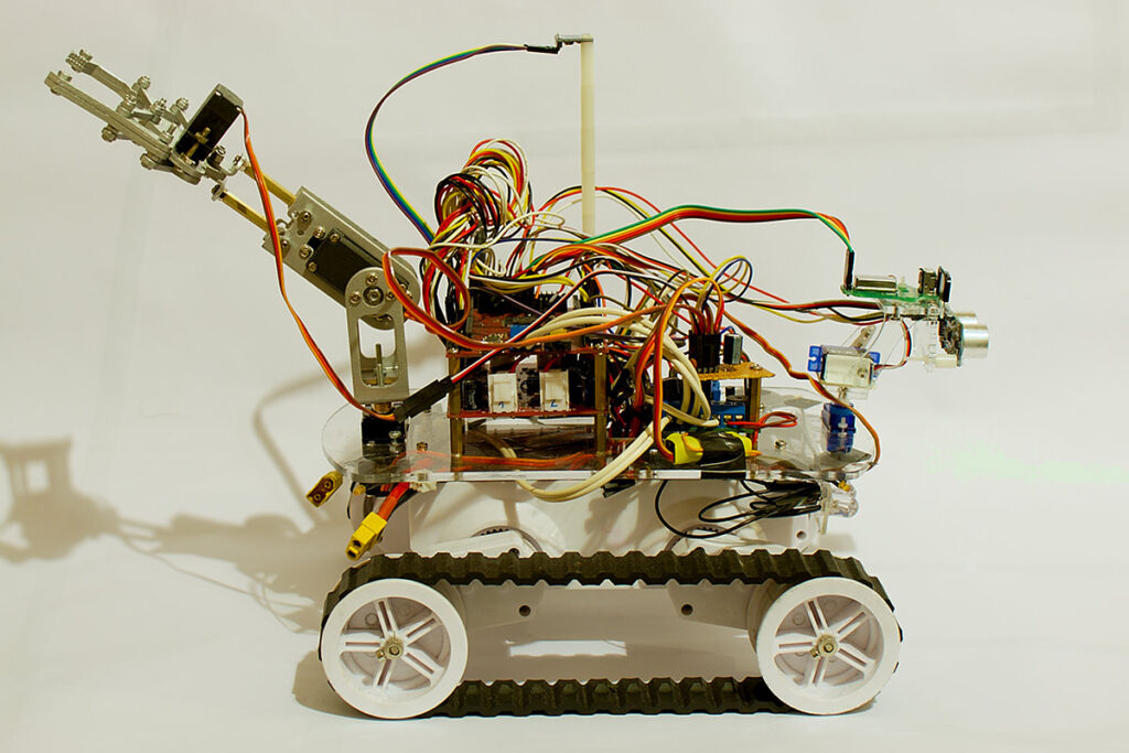
I’ve been rewriting the remote control code for my Dagu Rover 5. I wanted to integrate my encoder code in to my remote control sketch. In my old code I would directly scale the joystick values to a pwm value. Now I scale the joystick values to the time between encoder pulses. This is the “target pulse”. I then measure the time between pulses and and adjust the pwm accordingly. This gives the motors more torque and allows me to run them much slower. Which is very handy to accurately control the Rover.
I also recently modified the gripper, I’ve added another servo so that the gripper can rotate. The gripper now has 4 servos. The servos are powered by an 8A UBEC.
I’m still using a pair of nRF24L01 modules to remote control it with my self built Arduino remote. I used this fork of the RF24 library for the nRF24L01 modules.
You can download the code used in the above video here:
Sketch for remote
Rover 5 sketch
The Rover sketch starts with the radio code for the nRF24L01 module. I run this code once every 20ms. Running it faster gave me a lot of dropped packets. When the radio module hasn’t received a packet in more then 200ms the motors are stopped. I then read 5 analog inputs, the first one is the battery voltage. The Rover is powered by a 2S 3000mAh Lipo battery. The next 4 analog inputs are the current measurements of the 4 motors. If the battery voltage is high enough and the motors aren’t stalled the values from the joystick are processed to control the Rover and gripper. By pressing the joystick I can switch between controlling the motors and controlling the gripper. The remote has a 4×20 character LCD. The battery voltage of the Rover and the current of the motors are sent to the remote and displayed on the LCD.
Posted in Arduino sketches, Dagu Rover 5 | Tagged nRF24L01, robot |
By Bajdi on December 1, 2013
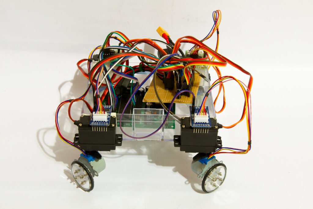
stepperbot
Chris from Rocket Brand Studios sent me 4 wheels that fit the little 28BYJ-48 stepper motors a couple of months ago. I only had 2 steppers so I ordered 2 more motors and control boards on Ebay. Cost me less then 2€ a piece, and that’s for the stepper motor and control board.
I wanted to try something different then the usual differential drive robots. Since I had a lot of spare servos I decided to fit the motors to 4 cheap MG995 servos. I just hot glued the 4 motors to the servo horns. I then used double sided tape to attach the servos and motors to a plastic box that is the chassis. This gives my robotic vehicle 4 wheel drive and 4 wheel steering.
The Arduino IDE comes with a stepper library, but I decided to write my own stepper code. For 4 stepper motors I would have needed 16 digital pins and then another 4 pins for the servos. Controlling a stepper motor is not that difficult. It’s just a matter of setting the pins high/low in the right sequence at the right time. I thought why not try and use a couple of 74HC595 shift registers to control the stepper motors? I have controlled 16 leds with 2 shift registers in the past so why not 4 stepper motors? I soldered 2 shift registers to a piece of perfboard and tested the board with some leds. That worked 🙂 There is an excellent tutorial that shows how to connect 2 74HC595 shift registers to an Arduino on the bildr.org website. The bildr tutorial also includes code on how to control each pin of a shift register individually. Based on that code I started writing a sketch that would let all 4 stepper motors run in the right direction.
These little stepper motors are slow and have very little torque. From what I have read they are manufactured to be used in the blinds of air-conditioning systems. To speed them up and give them some more power I used a 3S Lipo battery. This is well over the 5V at which these motors are rated. I have not killed a motor yet… Since they are so cheap it’s worth taking the risk. To let them run at a reasonable speed I had to write code to slowly ramp up the speed. Else the motors would not move.
This turned in to a huge sketch. The sketch in the following video contains over 1400 lines of code. There must be a much easier way of coding this? You can download the sketch here: 4 wheel drive and 4 wheel steering stepper bot sketch.
Posted in Arduino sketches | Tagged 28BYJ-48, 74HC595, robot |
By Bajdi on November 17, 2013
Dagu Rover 5
I’ve dusted of my Dagu Rover 5 🙂 While I’ve had my Rover 5 for almost 2 years I’ve never really used the encoders. Unfortunately my Rover 5 was delivered with an encoder that didn’t work right. So I decided to have a look at it and try to fix it. It turned out to be an easy fix. I just needed to adjust the potentiometer on the encoder control board. So now I had 4 working encoders 🙂
I’m using the Dagu 4 channel motor controller and a Dagu Red Back Spider controller on my Rover 5. The Rover 5 is fitted with 4 quadrature encoders. The 4 channel motor controller has 4 mixing circuits for the encoders. The mixing circuit takes the 2 inputs from the quadrature encoder and mixes them into a single output. So I needed to connect the 4 outputs of the mixing circuits to my Red Back Spider. The Red Back spider is based on the ATmega1280 micro controller (Arduino Mega) which has 6 external interrupts. I used interrupt 0 (pin D2), interrupt 1 (pin D3), interrupt 4 (pin D19) and interrupt 5 (pin D18). Interrupt 2 and 3 are also the I2C pins, I’m already using them for my digital compass.
I started with the same code as I had written for my other robot and changed it for 4 motors.
Next step is to integrate this code in my “Rover 5 remote control sketch”.
// http://www.bajdi.com
// Rover 5: 4 motors / 4 encoders
// Encoder speed control
// µController = ATmega1280

volatile unsigned long PulseM[4];   // Time between pulses
volatile unsigned long TimeM[4];  // Time when the last pulse got in
unsigned long lastPulseM[4] = {10000,10000,10000,10000};  // Time since the last pulse
const int targetPulse =  8500;  // THIS INTEGER CONTROLS THE SPEED OF THE MOTORS (900 fastest - 8500 slowest)

const int DirM[4] = {
  30,31,32,33}; // direction pins
const int PWMpinM[4] = {
  4,5,6,7};  // pwm pins
int PWMM[4];  // pwm settings

#define runEvery(t) for (static typeof(t) _lasttime;(typeof(t))((typeof(t))millis() - _lasttime) > (t);_lasttime += (t))

void setup()
{
  Serial.begin(115200);
  //Setup motor pins
  for(int i=0; i<4; i++)
  {
    pinMode(DirM[i], OUTPUT);
  }
  for(int i=0; i<4; i++)
  {
    pinMode(PWMpinM[i], OUTPUT);
  }
  // Setup encoder pins
  attachInterrupt(0,M1encoder,CHANGE);   // pin D2
  attachInterrupt(1,M2encoder,CHANGE);   // pin D3
  attachInterrupt(4,M3encoder,CHANGE);   // pin D19
  attachInterrupt(5,M4encoder,CHANGE);   // pin D18
}

void loop(void)
{
  for (int i=0; i<4; i+=1)
  {
    lastPulseM[i] = micros() - TimeM[i];
    if (lastPulseM[i] > targetPulse)
    {
      PWMM[i]+=1;
      if(PWMM[i] > 200)                   // Max pwm speed = 200
      {
        PWMM[i] = 200;
      }
    }
    if (lastPulseM[i] < targetPulse)
    {
      PWMM[i]-=1;
      if (PWMM[i] < 0)
      {
        PWMM[i] = 0;
      }
    }
    digitalWrite(DirM[i], HIGH);
    analogWrite(PWMpinM[i], PWMM[i]);
  }

  // serial printing
  runEvery(500){
    for (int i=0; i<4; i +=1)
    {
      Serial.print("PulseM = ");
      Serial.println(PulseM[i]);
    }
    for (int i=0; i<4; i +=1)
    {
      Serial.print("PWMM = ");
      Serial.println(PWMM[i]);
    }
  }
}

void M1encoder()
{
  PulseM[0]=micros()-TimeM[0];              // time between last state change and this state change
  TimeM[0]=micros();                        // update TimeM[0] with time of most recent state change
}

void M2encoder()
{
  PulseM[1]=micros()-TimeM[1];
  TimeM[1]=micros();
}

void M3encoder()
{
  PulseM[2]=micros()-TimeM[2];
  TimeM[2]=micros();
}

void M4encoder()
{
  PulseM[3]=micros()-TimeM[3];
  TimeM[3]=micros();
}
Posted in Arduino sketches, Dagu Rover 5 | Tagged encoder |