Bajdi electronics

Hobby electronics website

Browse: Page 30

Dagu Rover 5 remote control with nRF24L01

By Bajdi on April 13, 2012

Dagu Rover 5 remote control with nRF24L01 from Bajdi on Vimeo.

I have updated my sketch to remote control the Rover 5. There were a couple of things I wanted to try out. The Dagu 4 channel motor controller I use is equipped with 4 current outputs. These outputs give a 0 to 5V signal, 5V equals 5A. I hooked up all 4 sensor outputs to 4 analog inputs on the Red back spider. To know how much amps a motor draws the analogread value is divided by 1023 and then multiplied by 5.

Another thing I wanted to try was sending back data from the Rover to my remote using the RF24 Arduino library. This is very handy when you’re testing new code. Attaching a USB cable to your Rover while it’s driving around is not very practical. This gave me some trouble, when I originally wrote the sketch I had a lot of serial.print lines in the code and my sketch worked. When I removed these serial.print statements the sketch stopped working. Very strange and it took me a long time to figure out. When I replaced the serial.print statements with a tiny delay the code worked. To make this delay I did not use the delay function, but used the code from the “blink without delay” example sketch. You don’t want to have delay statements in code for a remote controlled vehicle, I tried it and it made my Rover very unresponsive.

After getting this to work I attached an I2C LCD to my “remote” so I could print the motor current values to it. I only have had an 2×16 lcd and after printing the 4 values to the lcd there is no more space for other stuff. I’ve just received a 4×20 I2C LCD, cost me 20$ on Ebay. This gives me some more “room” to play with. As you can see in the video my Rover 5 has become a big cable mess, should do something about that 🙂

Here is the sketch that I’m using for the remote:

// http://www.bajdi.com
// Nrf24L01 connected to Arduino Uno
// Nrf24L01 connection details http://arduino-info.wikispaces.com/Nrf24L01-2.4GHz-HowTo
// Transmit analog values from joystick to the receiver using RF24 library
// Receive 4 floats (current from the motors) from Rover 5 motor controller

#include <SPI.h>
#include <nRF24L01.h>
#include "RF24.h"
#include <Wire.h>
#include <LiquidCrystal_I2C.h>
#include <Bounce.h>

LiquidCrystal_I2C lcd(0x27,16,2); // set the LCD address to 0x27

RF24 radio(8,7);

const uint64_t pipes[2] = { 
  0xF0F0F0F0E1LL, 0xF0F0F0F0D2LL };

int joystick[3];
float current[4];

const int z = 2;
int roverState = LOW;         // the current state of the output pin

Bounce bouncer = Bounce( z, 5 );

long previousMillis = 0;
long interval = 25;

void setup(){
  pinMode(z, INPUT);
  radio.begin();
  radio.openWritingPipe(pipes[0]);
  radio.openReadingPipe(1,pipes[1]);
  radio.startListening();

  lcd.init(); // initialize the lcd
  lcd.backlight();
  lcd.setCursor(0,0);
  lcd.print("M1=");
  lcd.setCursor(8,0);
  lcd.print("M2=");
  lcd.setCursor(0,1);
  lcd.print("M3=");
  lcd.setCursor(8,1);
  lcd.print("M4=");

}

void loop(){
  joystick[0] = analogRead(A0);
  joystick[1] = analogRead(A1);
  joystick[2] = roverState;

  if ( bouncer.update() ) {
    if ( bouncer.read() == HIGH) {
      if ( roverState == LOW ) {
        roverState = HIGH;
      } 
      else {
        roverState = LOW;
      }
    }
  }

  if ( radio.available() )
  {
    unsigned long currentMillis = millis();

  if(currentMillis - previousMillis > interval) {
    previousMillis = currentMillis;   
    
    // Dump the payloads until we've gotten everything
    bool done = false;
    while (!done)
    {
      // Fetch the payload, and see if this was the last one.
      done = radio.read( &current, sizeof(current) );

    }
  }

    lcd.setCursor(3,0);
    lcd.print(current[0]);
    lcd.setCursor(11,0);
    lcd.print(current[1]);
    lcd.setCursor(3,1);
    lcd.print(current[2]);
    lcd.setCursor(11,1);
    lcd.print(current[3]);

    radio.stopListening();

    bool ok = radio.write( &joystick, sizeof(joystick) );

    radio.startListening();  

  }
} 

This is the sketch that goes in the Red back spider that controls the Rover 5:

// http://www.bajdi.com
// Dagu Rover 5 chassis with 4 motors
// Remote control through Nrf24L01 2,4GHz wireless module
// µcontroller = Dagu Red back spider, Arduino Mega 1280 compatible
// Motor controller = Dagu 4 channel motor controller
// Motor 1 and 2 on the left
// Motor 3 and 4 on the right
// Sent 4 floats (motor current) to transmitter (remote)

#include <SPI.h>
#include <nRF24L01.h>
#include "RF24.h"
#include "Ultrasonic.h"
#include <VarSpeedServo.h>

/* Nrf24L01 pinout
 1 GND
 2 VCC (3,3V)
 3 CE    pin 48 on Mega 1280
 4 CSN   pin 49 on Mega 1280
 5 SCK   pin 52 on Mega 1280
 6 MOSI  pin 51 on Mega 1280
 7 MISO  pin 50 on Mega 1280
 8 IRQ (not used)
 */

RF24 radio(48,49);
const uint64_t pipes[2] = { 
  0xF0F0F0F0E1LL, 0xF0F0F0F0D2LL };

int DirM1 = 30; // direction motor 1
int DirM2 = 31; // direction motor 2
int DirM3 = 32; // direction motor 3
int DirM4 = 33; // direction motor 4
int PWMM1 = 4;  // pwm motor 1
int PWMM2 = 5;  // pwm motor 2
int PWMM3 = 6;  // pwm motor 3
int PWMM4 = 7;  // pwm motor 4

int fs; // forward speed
int bs; // backward speed
int ls; // turn left speed
int rs; // turn right speed

int bat; // analog reading of battery voltage through voltage divider
const int lowbat = 34; // low battery led (red)
const int buzzer = 35; // buzzer
const int orange = 38; // orange leds
const int headlight = 39; // white leds

const int  TRIG = 36;
const int  ECHO = 37;

Ultrasonic SRF6A(TRIG, ECHO);

VarSpeedServo SRF6AServo;        // servo objects

int servoSpeeds = 30; // sweep speed, 1 is slowest, 255 fastest)
int servoMinPosition = 20; // the minumum servo angle
int servoMaxPosition = 110; // the maximum servo angle

int joystick[3];    // Array with 2 analog values (X,Y-axis) and one digital (Z-axis) from transmitter/joystick
float current[4];   // Array with the 4 motor current values, to sent to remote control

int apin[] = { 
  A1, A2, A3, A4 };  // analog pin array

long previousMillis = 0;

long interval = 25;

void setup() {
  pinMode(DirM1, OUTPUT);  // direction motor 1, left front
  pinMode(DirM2, OUTPUT);  // direction motor 2, left rear
  pinMode(DirM3, OUTPUT);  // direction motor 3, right front
  pinMode(DirM4, OUTPUT);  // direction motor 4, right rear
  pinMode(PWMM1, OUTPUT);  // PWM motor 1
  pinMode(PWMM2, OUTPUT);  // PWM motor 2
  pinMode(PWMM3, OUTPUT);  // PWM motor 3
  pinMode(PWMM4, OUTPUT);  // PWM motor 4
  pinMode(lowbat, OUTPUT); // low battery led (red)
  pinMode(buzzer, OUTPUT); // buzzer
  pinMode(orange, OUTPUT); // orange leds
  pinMode(headlight, OUTPUT); // white leds

  SRF6AServo.attach(8);       
  SRF6AServo.slowmove(servoMinPosition,servoSpeeds) ; // start sweeping from min position

  radio.begin();
  radio.openWritingPipe(pipes[1]);
  radio.openReadingPipe(1,pipes[0]);
  radio.startListening();
}

void loop() {

  bat = analogRead(A0);

  if (bat < 760)       // 760 / 1023 * 5 * 2 = 7,4V from battery  
  {
    digitalWrite(lowbat, HIGH);
  }
  else
  {
    digitalWrite(lowbat, LOW);
  }

  if ( radio.available() )
  {
    // Dump the payloads until we've gotten everything
    bool done = false;
    while (!done)
    {
      // Fetch the payload, and see if this was the last one.
      done = radio.read( &joystick, sizeof(joystick) );
    }
    if (bat > 760 && joystick[2] == HIGH)       // 760 / 1023 * 5 * 2 = 7,4V from battery  
    {
      digitalWrite(headlight, HIGH); // turn on headlights

      if( SRF6AServo.read() == servoMinPosition)
      {
        SRF6AServo.slowmove(servoMaxPosition,servoSpeeds) ; 
      }       
      else if( SRF6AServo.read() == servoMaxPosition)
      {
        SRF6AServo.slowmove(servoMinPosition,servoSpeeds) ; 
      }     

      if(SRF6A.Ranging(CM) < 5){
        digitalWrite(buzzer, HIGH);      // we're going to crash 
      }
      else {
        digitalWrite(buzzer, LOW); 
      } 

      if (joystick[0] > 500 && joystick[0] < 540 && joystick[1] > 490 && joystick[1] < 530 )    // joystick is centered
      {
        stopped();
      }

      if (joystick[0] <= 500 && joystick[1] > 490 && joystick[1] < 530)               // joystick forward = all motors forward
      {
        fs = (map(joystick[0], 500, 0, 35, 255));
        forward(fs);
      }

      if (joystick[0] >= 540 && joystick[1] > 490 && joystick[1] < 530)               // joystick backward = all motors backward
      {
        bs = (map(joystick[0], 540, 1023, 35, 255));
        backward(bs);
      }

      if (joystick[1] <= 490 && joystick[0] > 500 && joystick[0] < 540)              // joystick left = left motors backward && right motors forward
      {
        ls = (map(joystick[1], 490, 0, 35, 255));
        turnleft(ls);
      }

      if (joystick[1] >= 530 && joystick[0] > 500 && joystick[0] < 540)              // joystick right = left motors forward && right motors backward
      {
        rs = (map(joystick[1], 530, 1023, 35, 255));
        turnright(rs);
      }
    }
    else {
      stopped();
      digitalWrite(headlight, LOW); // turn off headlights
    }
  }

  // 4 analog readings from motor controller = motor current
  for (int i=0; i<4; i++)
  {
    current[i] = analogRead( apin[i] )/ 1023.0 * 5.0;
  }

  unsigned long currentMillis = millis();

  if(currentMillis - previousMillis > interval) {
    previousMillis = currentMillis;   

    radio.stopListening();
    bool ok = radio.write( &current, sizeof(current) );
    radio.startListening();
  }
}

void stopped()
{
  analogWrite(PWMM1, 0);
  analogWrite(PWMM2, 0);
  analogWrite(PWMM3, 0);
  analogWrite(PWMM4, 0);
  digitalWrite(orange, LOW);
}

void forward(int fs)
{
  digitalWrite(DirM1, HIGH);
  digitalWrite(DirM2, HIGH);
  digitalWrite(DirM3, HIGH);
  digitalWrite(DirM4, HIGH);
  analogWrite(PWMM1, fs);
  analogWrite(PWMM2, fs);
  analogWrite(PWMM3, fs);
  analogWrite(PWMM4, fs);
  digitalWrite(orange, LOW);
}

void backward(int bs)
{
  digitalWrite(DirM1, LOW);
  digitalWrite(DirM2, LOW);
  digitalWrite(DirM3, LOW);
  digitalWrite(DirM4, LOW);
  analogWrite(PWMM1, bs);
  analogWrite(PWMM2, bs);
  analogWrite(PWMM3, bs);
  analogWrite(PWMM4, bs);
  digitalWrite(orange, LOW);
}

void turnleft(int ls)
{
  digitalWrite(DirM1, LOW);
  digitalWrite(DirM2, LOW);
  digitalWrite(DirM3, HIGH);
  digitalWrite(DirM4, HIGH);
  analogWrite(PWMM1, ls);
  analogWrite(PWMM2, ls);
  analogWrite(PWMM3, ls);
  analogWrite(PWMM4, ls);
  digitalWrite(orange, HIGH);
}

void turnright(int rs)
{
  digitalWrite(DirM1, HIGH);
  digitalWrite(DirM2, HIGH);
  digitalWrite(DirM3, LOW);
  digitalWrite(DirM4, LOW);
  analogWrite(PWMM1, rs);
  analogWrite(PWMM2, rs);
  analogWrite(PWMM3, rs);
  analogWrite(PWMM4, rs);
  digitalWrite(orange, HIGH);
}

These sketches are becoming rather big, the transmitter sketch is more then 9000 bytes and the Rover 5 sketch is over 11000 bytes. The Dagu red back spider controller is based on the ATmega 1280 and has 128kb (minus the bootloader) of memory, I don’t think I will ever have to worry about running out of space 🙂
The transmitter or remote I currently use is an Arduino Duemilanove with a sensor shield on top of it. There is a nRF24L01 module, small joystick and I2C LCD display connected to it. You can find a picture of it here. The only thing that holds it all together are the wires connecting everything. So I’ve decided to make an enclosure for all these parts, I will have some plexiglass cut up to fit it all. I’ve ordered a joystick shield with some more buttons on it (always handy). And I’ve already received a 2×20 I2C LCD display, I will use a small 2 cell 500mAh Lipo battery to power it all. I bought 2 small 2 cell 500mAh Lipo batteries for 12,5€ on Ebay. I prefer them to AA batteries.
Posted in Arduino sketches, Dagu Rover 5 | Tagged nRF24L01, robot | 7 Responses

Rover 5 autonomous mode part 2

By Bajdi on April 10, 2012

Dagu Rover 5 in autonomous mode from Bajdi on Vimeo.

Since my Rover 5 has 4 encoders I wanted to do something with these encoders. There is an encoder library for Arduino which makes it very easy to read the encoders. I first tried the example sketches that come with the library to check if my encoders where working. So I thought of making a sketch to let the Rover drive autonomous and when it detects an object it does a 90° turn. The 90° turn equals xx number of pulses from the encoders. Sounds more simple then it is, I got some help from the friendly people at letsmakerobots.com. I made 2 sketches, one where the Rover always does a 90° turn to the left after it has detected an object and one where I use a servo to turn the ultrasonic sensor left/right and then decide in which direction the Rover should turn. This last sketch does not work very well. I use the delay function after sending the command to the servo. During this delay the reading from the encoders stops. Another thing to take into account is that the tracks of the Rover slip depending on the surface. So it’s not really possible to determine how many pulses you exactly need for a 90° turn.

I’ve added some leds to my Rover 5, 6 white 10mm leds on the front and 4 3mm orange leds on the corners. The white leds get their power through a NPN transistor that is controlled by the Red back spider controller. The orange leds are connected to a NE555 chip, the supply of that chip is also controlled from a NPN transistor connected to the Red back spider controller.

This is the sketch where the Rover will turn 90° to the left when an object is detected:

// http://www.bajdi.com
// Dagu Rover 5 chassis with 4 motors
// Autonomous mode using an SRF06 ultrasonic sensor
// Using one encoder to do 90° turns when an object is detected (80 pulses = 90°)
// µcontroller = Dagu Red back spider, Arduino Mega 1280 compatible
// Motor controller = Dagu 4 channel motor controller
// Motor 1 and 2 on the left
// Motor 3 and 4 on the right

#include "Ultrasonic.h"
#include <Encoder.h>

const int DirM1 = 30; // direction motor 1
const int DirM2 = 31; // direction motor 2
const int DirM3 = 32; // direction motor 3
const int DirM4 = 33; // direction motor 4
const int PWMM1 = 4;  // pwm motor 1
const int PWMM2 = 5;  // pwm motor 2
const int PWMM3 = 6;  // pwm motor 3
const int PWMM4 = 7;  // pwm motor 4

const int  TRIG = 36;
const int  ECHO = 37;

int bat; // analog reading of battery voltage through voltage divider
const int lowbat = 34; // low battery led (red)
const int buzzer = 35; // buzzer
const int orange = 38; // orange leds
const int headlight = 39; // white leds
const int leftled = 40; // red led

Ultrasonic SRF6A(TRIG, ECHO);

Encoder encl(2, 3);

const int ATTENTION_DISTANCE = 25;
const int NINETY_DEGREES = 80;

int currentDegrees = 0;
int lastPulse = 0;
int left;
int right;

void setup() {
  pinMode(DirM1, OUTPUT);  // direction motor 1, right front
  pinMode(DirM2, OUTPUT);  // direction motor 2, right rear
  pinMode(DirM3, OUTPUT);  // direction motor 3, left front
  pinMode(DirM4, OUTPUT);  // direction motor 4, left rear
  pinMode(PWMM1, OUTPUT);  // PWM motor 1
  pinMode(PWMM2, OUTPUT);  // PWM motor 2
  pinMode(PWMM3, OUTPUT);  // PWM motor 3
  pinMode(PWMM4, OUTPUT);  // PWM motor 4
  pinMode(lowbat, OUTPUT); // low battery led (red)
  pinMode(buzzer, OUTPUT); // buzzer
  pinMode(orange, OUTPUT); // orange leds
  pinMode(headlight, OUTPUT); // white leds
  pinMode(leftled, OUTPUT);   // red led
  delay(200);
  forward(); 
}

void loop() {

  digitalWrite(headlight, HIGH);

  bat = analogRead(A0);

  if (bat > 765){          // 765 / 1023 * 5 * 2 = 7,4V from battery  

    if(SRF6A.Ranging(CM) < 10){
      digitalWrite(buzzer, HIGH);      // we're going to crash 
    }
    else {
      digitalWrite(buzzer, LOW); 
    } 

    if(isAttention()){
      turnleft();
    }
    if(isTurnFinished()){
      resetDegreeMeasurement();
      forward();
    }
    else{
      measureDegrees();
    }
  }
  else {
    stopped();
    digitalWrite(lowbat, HIGH);
  }
}

boolean isAttention(){
  int distance = SRF6A.Ranging(CM);

  if(distance > ATTENTION_DISTANCE){
    return false;
  }
  return true;
}

void measureDegrees(){

  int pulse = readPulse();
  if(pulse == lastPulse){

    return;
  }
  lastPulse = pulse;
  currentDegrees++;  
}

int readPulse(){
  return encl.read();
}

boolean isTurnFinished(){ 
  return (currentDegrees == NINETY_DEGREES);
}

void resetDegreeMeasurement(){
  currentDegrees = 0;
}

void forward()
{
  digitalWrite(DirM1, LOW);
  digitalWrite(DirM2, LOW);
  digitalWrite(DirM3, LOW);
  digitalWrite(DirM4, LOW);
  analogWrite(PWMM1, 65);
  analogWrite(PWMM2, 65);
  analogWrite(PWMM3, 65);
  analogWrite(PWMM4, 65);
  digitalWrite(orange, LOW);
  digitalWrite(leftled, LOW);
}

void turnleft()
{
  digitalWrite(DirM1, LOW);
  digitalWrite(DirM2, LOW);
  digitalWrite(DirM3, HIGH);
  digitalWrite(DirM4, HIGH);
  analogWrite(PWMM1, 80);
  analogWrite(PWMM2, 80);
  analogWrite(PWMM3, 80);
  analogWrite(PWMM4, 80);
  digitalWrite(orange, HIGH);
  digitalWrite(leftled, HIGH);
}  

void stopped()
{
  analogWrite(PWMM1, 0);
  analogWrite(PWMM2, 0);
  analogWrite(PWMM3, 0);
  analogWrite(PWMM4, 0);
  digitalWrite(orange, LOW);
  digitalWrite(leftled, LOW);
}

Posted in Dagu Rover 5 | Tagged robot, ultrasonic | Leave a response

Arduino rc car part 1 motor control

By Bajdi on March 26, 2012

L298n board

L298n board

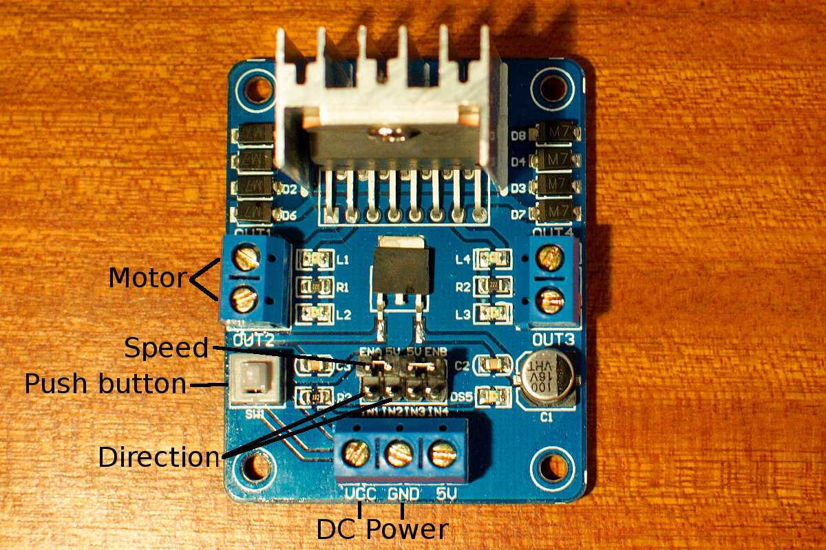
I still have an old Nikko RC car from about 20 years ago. It has lost it’s body and looks very dusty. I plugged in some fresh batteries but I doesn’t work anymore, the electronics are dead. So I’m going to try getting it back to life by putting an Arduino on it. I’ve already bought a small board with a L298n chip to supply power to the main motor. To remote control the car I will use a pair of nRF24L01 modules. One thing I haven’t figured out for sure is how I’m going to turn the front wheels. There is an ancient servo on it that turns the wheels, the servo looks like a big coil. By providing 7V to it turns the front wheels, reversing the polarity changes the direction. So I think I can also use this servo with the L298n chip. That’s on my to do list 🙂 First thing I tried was hooking up the motor to the L298n board. I bought this board on Ebay for less then 10$, it didn’t come with any instructions on how to connect it to a microcontroller.

After taking a good look at it I noticed that it has an onboard 5V regulator. Although there is a 5V terminal you don’t need to connect it. By pushing the little button on the left you select the onboard regulator, when it’s not pushed in you need to supply 5V for the logic of the L298n. I connected my lab power supply to the VCC terminal and GND, the GND is also connected to the Arduino. Then I connected the 2 wires from the motor to OUT1 and OUT2. You need 3 pins on the Arduino to control the L298n, 2 digital outputs to select direction and 1 PWM output to control the speed of the motor. I connected pins 2 and 4 to IN1 and IN2, the state of these pins will give the direction. PWM pin 3 is connected to ENA to control the speed of the motor. I wrote a small sketch to test the motor. I connected a 10K potentiometer to analog input 0 on my Arduino Uno and mapped the value of the potentiometer to control the speed and direction of the motor.

Here is the sketch:

// http://www.bajdi.com
// Potentiometer controlling small dc motor through standalone L298n board

const int in1 = 2;    // direction pin 1
const int in2 = 4;    // direction pin 2
const int ena = 3;    // PWM pin to change speed

int pot;              // integer for potentiometer
int fspeed;           // forward speed 
int bspeed;           // backward speed

void setup() {
  pinMode(in1, OUTPUT);
  pinMode(in2, OUTPUT);
  pinMode(ena, OUTPUT);
}

void loop() {
  pot = analogRead(A0);

  if (pot >= 480 && pot <= 540)
  {
    stop();
  }
  if (pot < 500)
  {
    fspeed = map(pot, 479, 0, 70, 250);
    forward(fspeed);
  }
  if (pot > 520)
  {
    bspeed = map(pot, 541, 1023, 70, 250);
    backward(bspeed);
  }
}

void stop()
{
  analogWrite(ena, 0);
}

void forward(int fspeed)
{
  digitalWrite(in1, HIGH);
  digitalWrite(in2, LOW);
  analogWrite(ena, fspeed);
}

void backward(int bspeed)
{
  digitalWrite(in1, LOW);
  digitalWrite(in2, HIGH);
  analogWrite(ena, bspeed);
}

I mapped the PWM value starting from 70 because at a lower value the motor would not turn.

Posted in Arduino sketches | Tagged L298 | 1 Response

« PreviousNext »

Recent Posts

  • 3D Printer extruders
  • Mearm forked
  • Arduino time lapse – camera pan device
  • Bought a 199$* Prusa I3 3D printer
  • Simple DIY lab power supply
  • Bajduino
    • Bajduino 1284
    • Bajduino 328
  • Stepper robot arm

Recent Comments

  1. 200+ Arduino Projects List For Final Year Students - He Loves Math on Obstacle avoiding robot made from cheap parts
  2. MP3 Alarm Clock: Crafting Customized wake-Up tunes with Arduino on Arduino MP3 alarm clock
  3. Bas on L9110 H-bridge module
  4. Victor on L9110 H-bridge module
  5. WAQAR AHMED on Dimming led with IR remote control

Archives

  • June 2016
  • August 2015
  • May 2015
  • January 2015
  • December 2014
  • November 2014
  • May 2014
  • April 2014
  • March 2014
  • February 2014
  • January 2014
  • December 2013
  • November 2013
  • October 2013
  • September 2013
  • June 2013
  • May 2013
  • April 2013
  • March 2013
  • February 2013
  • January 2013
  • December 2012
  • November 2012
  • October 2012
  • September 2012
  • August 2012
  • July 2012
  • June 2012
  • May 2012
  • April 2012
  • March 2012
  • February 2012
  • January 2012
  • December 2011

Categories

  • 3D printing
  • Arduino
  • Arduino sketches
  • Bajdupod 996R
  • Bajdupod 9G
  • Bob the biped
  • Buying parts
  • Dagu Rover 5
  • Dagu service droid
  • Gentoo
  • Insectbot
  • Line following robot
  • Raspberry Pi
  • Self balancing bot
  • Bajduino
    • Bajduino 1284
    • Bajduino 328
  • Stepper robot arm

Copyright © 2026 Bajdi electronics.

Powered by WordPress and Hybrid by Bajdi.