Bajdi electronics

Hobby electronics website

Browse: Page 31

RF24 library revisited

By Bajdi on March 17, 2012

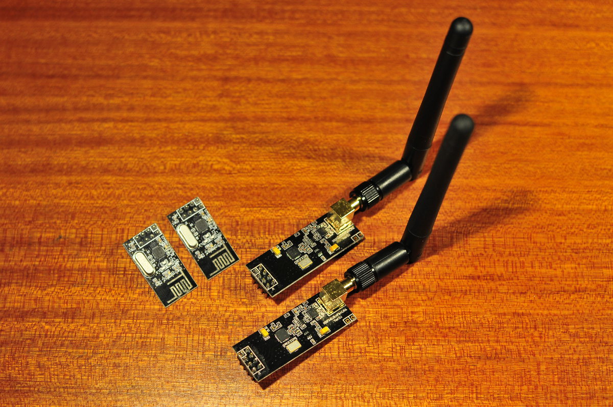
nRF24L01 wireless radio modules

nRF24L01 wireless radio modules


A while ago I started playing with a couple of nRF24L01 modules. I found 2 Arduino libraries, the Mirf library which is available on the Arduino playground and Maniacbugs RF24 library. I spent quite some time getting these things to work without much success. Eventually I got them to work with the Mirf library. I later made several sketches to control my Rover 5 and kept using the Mirf library. Today I made another attempt to get my nRF24L01 modules to work with the RF24 library and this time I succeeded. I made 2 sketches, one for the receiver and one for the transmitter. The transmitter sketch transmits 2 analog values from a joystick to the receiver. These are 2 very basic sketches using the RF24 library. They might be helpful for people like me who haven’t much experience with programming. I found the example sketches that come with the RF24 library quite difficult to understand.
Transmitter sketch:

 /*
http://www.bajdi.com
This sketch transmits 2 analog values through an nRF24L01 wireless module.
*/

#include <SPI.h>
#include "nRF24L01.h"
#include "RF24.h"

int joystick[2];

RF24 radio(8,7);

const uint64_t pipe = 0xE8E8F0F0E1LL;

void setup(void)
{
  Serial.begin(9600);
  radio.begin();
  radio.openWritingPipe(pipe);
}

void loop(void)
{
  joystick[0] = analogRead(A0);
  joystick[1] = analogRead(A1);
 
  radio.write( joystick, sizeof(joystick) );

}

This is the receiver sketch:

/*
 http://www.bajdi.com
 This sketch receives 2 analog values through an nRF24L01 wireless module.
 */

#include <SPI.h>
#include "nRF24L01.h"
#include "RF24.h"

int joystick[2];

RF24 radio(48,49);
const uint64_t pipe = 0xE8E8F0F0E1LL;

void setup(void)
{
  Serial.begin(9600);
  radio.begin();
  radio.openReadingPipe(1,pipe);
  radio.startListening();
}

void loop(void)
{
  if ( radio.available() )
  {
    // Dump the payloads until we've gotten everything
    bool done = false;
    while (!done)
    {
      // Fetch the payload, and see if this was the last one.
      done = radio.read( joystick, sizeof(joystick) );
      Serial.println(joystick[0]);
      Serial.println(joystick[1]);
    }
  }
  else
  {
    Serial.println("No radio available");
  }
}

Posted in Arduino sketches | Tagged nRF24L01 | 37 Responses

Continuous rotation servos and Arduino

By Bajdi on March 14, 2012

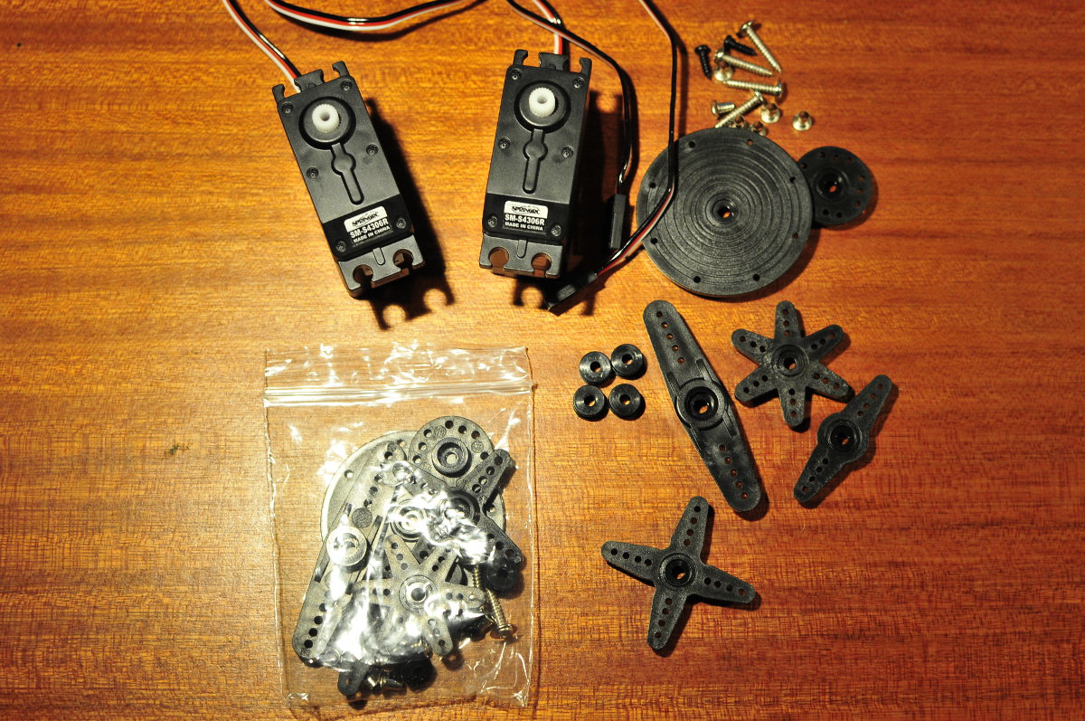
SM-S4306R continuous rotation servo

SM-S4306R continuous rotation servo

I have 2 SpringRC SM-S4306R servos, these are continuous rotation servos with plastic gears. You can find them for less then 10$, I got mine on Ebay. These servos come with a bag of attachments, I got no less then 6 different plastic attachments. The difference with a standard servo is that these will continue to rotate while a standard servo will just go to a certain position and then hold that position. So these servos can be used to drive a wheel of a robot. They have the same 3 wire connector as a standard servo, VCC, GND and one wire to control the servo. On the side of these servos there is a screw, by turning this screw you can setup the “zero” position of the servo. This is important to accurately control the servo. When you do servo.write(90) the servo should be at standstill.

Both of my servos needed some finetuning so they would stop at the 90 degree position. To do that I just made a simple sketch with servo.write(90) in it. Then I adjusted the screw so that the servo didn’t move any more. Continuous servos work with the same servo library that comes with the Arduino IDE as standard servos, you don’t need any special libraries. To rotate the servo you just write a value to it, 90 is stop, a value lower then 90 is counterclockwise a value bigger then 90 is clockwise. I checked how much current these servos draw, at full speed they draw 120mA @ 6V.
When starting or when quickly changing the direction they draw a lot more current, I’ve seen peaks of almost 400mA. So you need an adequate power supply to power them, do not power them straight of an Arduino.

I’ve seen some posts on the Arduino forum from people that try to run servos of a 9V (6LR61) battery, these batteries can not supply enough current to power these servos. And you could potentially damage them because most servos are made for voltages between 4 and 6V. Compared to standard DC motors servos have the benefit that they don’t need any electronics or gearboxes to use them, servos have all these things onboard making them very easy to use. The downside is that it is difficult to find cheap wheels that mount directly to a servo. But you can find continuous servos with a wheel already attached to them, Arduino-direct sells them.

Here is a sketch that will let a continuous rotation servo turn in both directions at full speed and at a very slow speed:

// http://www.bajdi.com
// Rotating a continuous servo (tested with a SpringRC SM-S4306R)

#include <Servo.h> 
 
Servo myservo;  // create servo object to control a servo 
 
void setup() 
{ 
  myservo.attach(9);  // attaches the servo on pin 9 to the servo object 
} 
 
void loop() 
{ 
  
  myservo.write(45);                  // rotate counterclockwise full speed
  delay(2000);                           
  myservo.write(90);                  // stop
  delay(100);
  myservo.write(135);                 // rotate clockwise full speed
  delay(2000);
  myservo.write(90);                  // stop
  delay(100);
  myservo.write(80);                  // rotate very slowly counterclockwise
  delay(2000);
  myservo.write(90);                  // stop
  delay(100);
  myservo.write(100);                 // rotate very slowly clockwise
  delay(2000);
} 

Posted in Arduino sketches | Tagged servo | 13 Responses

Rover 5 autonomous mode

By Bajdi on March 9, 2012

Rover 5 in autonomous mode from Bajdi on Vimeo.

After writing a sketch to remote control the Rover 5 it was time to try and write a sketch to let it drive around the house autonomously. To keep things simple I used only one ultrasonic sensor for obstacle detection. My SRF06 ultrasonic module is mounted on a small micro 9G servo. I used the varspeedservo library to sweep the servo from left to right. My biggest problem was reading the distance from the ultrasonic sensor at a certain servo position (Servo.read() == xxx). When I sweeped the servo to fast I wouldn’t get any reading because the servo overshoots some positions. That took me some time to figure out. I tried lots of different things but in the end I just read the distance between two servo positions. This gave me the best results. My next step is to make use of the encoders that are fitted to the wheels. I want to make a sketch that when an obstacle is detected the Rover turns 90°. The 90° would be X number of pulses from the encoder.

I did have some trouble with my Rover 5 during the many test sessions. Suddenly one motor stopped spinning. I was already thinking the worst, maybe I had blown something up? After taking everything apart I found that one of the wires going from the noise suppression coil in the bottom of the chassis to the motor connector had come loose. I re soldered the wire and all was fine again. Then a wheel and axle came of the rover, the axle is only fixed by a plastic gear. I refitted the wheel but the axle has a lot of play. That seems to be the reason that the track keeps coming of.
Here is my first Rover 5 autonomous sketch, keep in mind that I’m new to programming and robots so the code is probably a very bad example. Comments on how to improve it are very welcome 🙂

// http://www.bajdi.com
// Dagu Rover 5 chassis with 4 motors
// Autonomous mode using an SRF06 ultrasonic sensor mounted on a 9G servo on the front
// µcontroller = Dagu Red back spider, Arduino Mega 1280 compatible
// Motor controller = Dagu 4 channel motor controller
// Motor 1 and 2 on the left
// Motor 3 and 4 on the right

#include "Ultrasonic.h"
#include <VarSpeedServo.h>

int DirM1 = 30; // direction motor 1
int DirM2 = 31; // direction motor 2
int DirM3 = 32; // direction motor 3
int DirM4 = 33; // direction motor 4
int PWMM1 = 3;  // pwm motor 1
int PWMM2 = 4;  // pwm motor 2
int PWMM3 = 5;  // pwm motor 3
int PWMM4 = 6;  // pwm motor 4

int bat; // analog reading of battery voltage through voltage divider
const int lowbat = 34; // low battery led (red)
const int buzzer = 35; // buzzer

const int  TRIG = 36;
const int  ECHO = 37;
Ultrasonic SRF6A(TRIG, ECHO);

int val1;
int val2;
int val3;
int val4;
int val5;
int valavg;

VarSpeedServo SRF6AServo;        // servo objects

int servoSpeeds = 25; // sweep speed, 1 is slowest, 255 fastest)
int servoMinPosition = 25; // the minumum servo angle
int servoMaxPosition = 105; // the maximum servo angle

void setup() {

  // Serial.begin(9600);

  pinMode(DirM1, OUTPUT);  // direction motor 1, left front
  pinMode(DirM2, OUTPUT);  // direction motor 2, left rear
  pinMode(DirM3, OUTPUT);  // direction motor 3, right front
  pinMode(DirM4, OUTPUT);  // direction motor 4, right rear
  pinMode(PWMM1, OUTPUT);  // PWM motor 1
  pinMode(PWMM2, OUTPUT);  // PWM motor 2
  pinMode(PWMM3, OUTPUT);  // PWM motor 3
  pinMode(PWMM4, OUTPUT);  // PWM motor 4
  pinMode(lowbat, OUTPUT); // low battery led (red)
  pinMode(buzzer, OUTPUT); // buzzer

  SRF6AServo.attach(7);       
  SRF6AServo.slowmove(servoMinPosition,servoSpeeds) ; // start sweeping from min position

}

void loop() {

  bat = analogRead(A1);

  if (bat <= 730)                 // 730 equals 7V (2 cell Lipo)
  {
    digitalWrite(lowbat, HIGH);   // battery low
  }


  if ( SRF6AServo.read() == servoMinPosition) 
  {
    SRF6AServo.slowmove(servoMaxPosition,servoSpeeds); 
  }
  if ( SRF6AServo.read() >= 25 && SRF6AServo.read() < 30)
  {
    val1 = SRF6A.Ranging(CM);
  }

  if ( SRF6AServo.read() > 52 && SRF6AServo.read() < 57) 
  {
    val2 = SRF6A.Ranging(CM);
  }

  if ( SRF6AServo.read() > 62 && SRF6AServo.read() < 67) 
  {
    val3 = SRF6A.Ranging(CM);
  }

  if ( SRF6AServo.read() > 72 && SRF6AServo.read() < 77) 
  {
    val4 = SRF6A.Ranging(CM);
  }

  if ( SRF6AServo.read() > 100 && SRF6AServo.read() < 105)
  {
    val5 = SRF6A.Ranging(CM);
  }
  if( SRF6AServo.read() == servoMaxPosition)
  {
    SRF6AServo.slowmove(servoMinPosition,servoSpeeds); 
  }

  valavg = ((val2 + val3 + val4) /3);

  /*
  Serial.print("val1 = ");
   Serial.println(val1);
   Serial.print("val2 = ");
   Serial.println(val2);
   Serial.print("val3 = ");
   Serial.println(val3);
   Serial.print("val4 = ");
   Serial.println(val4);
   Serial.print("val5 = ");
   Serial.println(val5);
   */

  if (val2 < 25 || val3 < 25 || val4 < 25 || valavg < 25)
  {

    if (val1 < val5)
    {
      turnright();
    }
    if (val5 < val1)
    {
      turnleft();
    }
  }
  else
  {
    forward();
  }

  if (valavg < 10)
  {
    digitalWrite(buzzer, HIGH);     // we're going to crash :)
  }
  else
  {
    digitalWrite(buzzer, LOW);
  }
}

void turnleft()
{
  digitalWrite(DirM1, LOW);
  digitalWrite(DirM2, LOW);
  digitalWrite(DirM3, HIGH);
  digitalWrite(DirM4, HIGH);
  analogWrite(PWMM1, 150);
  analogWrite(PWMM2, 150);
  analogWrite(PWMM3, 150);
  analogWrite(PWMM4, 150);
}

void turnright()
{
  digitalWrite(DirM1, HIGH);
  digitalWrite(DirM2, HIGH);
  digitalWrite(DirM3, LOW);
  digitalWrite(DirM4, LOW);
  analogWrite(PWMM1, 150);
  analogWrite(PWMM2, 150);
  analogWrite(PWMM3, 150);
  analogWrite(PWMM4, 150); 
}

void forward()
{
  digitalWrite(DirM1, HIGH);
  digitalWrite(DirM2, HIGH);
  digitalWrite(DirM3, HIGH);
  digitalWrite(DirM4, HIGH);
  analogWrite(PWMM1, 70);
  analogWrite(PWMM2, 70);
  analogWrite(PWMM3, 70);
  analogWrite(PWMM4, 70);
}
Posted in Arduino sketches, Dagu Rover 5 | Tagged robot, ultrasonic | 2 Responses

« PreviousNext »

Recent Posts

  • 3D Printer extruders
  • Mearm forked
  • Arduino time lapse – camera pan device
  • Bought a 199$* Prusa I3 3D printer
  • Simple DIY lab power supply
  • Bajduino
    • Bajduino 1284
    • Bajduino 328
  • Stepper robot arm

Recent Comments

  1. 200+ Arduino Projects List For Final Year Students - He Loves Math on Obstacle avoiding robot made from cheap parts
  2. MP3 Alarm Clock: Crafting Customized wake-Up tunes with Arduino on Arduino MP3 alarm clock
  3. Bas on L9110 H-bridge module
  4. Victor on L9110 H-bridge module
  5. WAQAR AHMED on Dimming led with IR remote control

Archives

  • June 2016
  • August 2015
  • May 2015
  • January 2015
  • December 2014
  • November 2014
  • May 2014
  • April 2014
  • March 2014
  • February 2014
  • January 2014
  • December 2013
  • November 2013
  • October 2013
  • September 2013
  • June 2013
  • May 2013
  • April 2013
  • March 2013
  • February 2013
  • January 2013
  • December 2012
  • November 2012
  • October 2012
  • September 2012
  • August 2012
  • July 2012
  • June 2012
  • May 2012
  • April 2012
  • March 2012
  • February 2012
  • January 2012
  • December 2011

Categories

  • 3D printing
  • Arduino
  • Arduino sketches
  • Bajdupod 996R
  • Bajdupod 9G
  • Bob the biped
  • Buying parts
  • Dagu Rover 5
  • Dagu service droid
  • Gentoo
  • Insectbot
  • Line following robot
  • Raspberry Pi
  • Self balancing bot
  • Bajduino
    • Bajduino 1284
    • Bajduino 328
  • Stepper robot arm

Copyright © 2026 Bajdi electronics.

Powered by WordPress and Hybrid by Bajdi.