I still have an old Nikko RC car from about 20 years ago. It has lost it’s body and looks very dusty. I plugged in some fresh batteries but I doesn’t work anymore, the electronics are dead. So I’m going to try getting it back to life by putting an Arduino on it. I’ve already bought a small board with a L298n chip to supply power to the main motor. To remote control the car I will use a pair of nRF24L01 modules. One thing I haven’t figured out for sure is how I’m going to turn the front wheels. There is an ancient servo on it that turns the wheels, the servo looks like a big coil. By providing 7V to it turns the front wheels, reversing the polarity changes the direction. So I think I can also use this servo with the L298n chip. That’s on my to do list 🙂 First thing I tried was hooking up the motor to the L298n board. I bought this board on Ebay for less then 10$, it didn’t come with any instructions on how to connect it to a microcontroller.
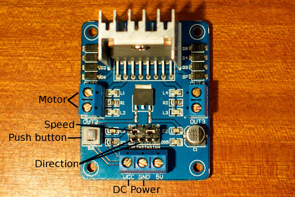
After taking a good look at it I noticed that it has an onboard 5V regulator. Although there is a 5V terminal you don’t need to connect it. By pushing the little button on the left you select the onboard regulator, when it’s not pushed in you need to supply 5V for the logic of the L298n. I connected my lab power supply to the VCC terminal and GND, the GND is also connected to the Arduino. Then I connected the 2 wires from the motor to OUT1 and OUT2. You need 3 pins on the Arduino to control the L298n, 2 digital outputs to select direction and 1 PWM output to control the speed of the motor. I connected pins 2 and 4 to IN1 and IN2, the state of these pins will give the direction. PWM pin 3 is connected to ENA to control the speed of the motor. I wrote a small sketch to test the motor. I connected a 10K potentiometer to analog input 0 on my Arduino Uno and mapped the value of the potentiometer to control the speed and direction of the motor.
Here is the sketch:
// http://www.bajdi.com
// Potentiometer controlling small dc motor through standalone L298n board

const int in1 = 2;    // direction pin 1
const int in2 = 4;    // direction pin 2
const int ena = 3;    // PWM pin to change speed

int pot;              // integer for potentiometer
int fspeed;           // forward speed
int bspeed;           // backward speed

void setup() {
  pinMode(in1, OUTPUT);
  pinMode(in2, OUTPUT);
  pinMode(ena, OUTPUT);
}

void loop() {
  pot = analogRead(A0);

  if (pot >= 480 && pot <= 540)
  {
    stop();
  }
  if (pot < 500)
  {
    fspeed = map(pot, 479, 0, 70, 250);
    forward(fspeed);
  }
  if (pot > 520)
  {
    bspeed = map(pot, 541, 1023, 70, 250);
    backward(bspeed);
  }
}

void stop()
{
  analogWrite(ena, 0);
}

void forward(int fspeed)
{
  digitalWrite(in1, HIGH);
  digitalWrite(in2, LOW);
  analogWrite(ena, fspeed);
}

void backward(int bspeed)
{
  digitalWrite(in1, LOW);
  digitalWrite(in2, HIGH);
  analogWrite(ena, bspeed);
}
I mapped the PWM value starting from 70 because at a lower value the motor would not turn.

do you have schematics for this please thank you!