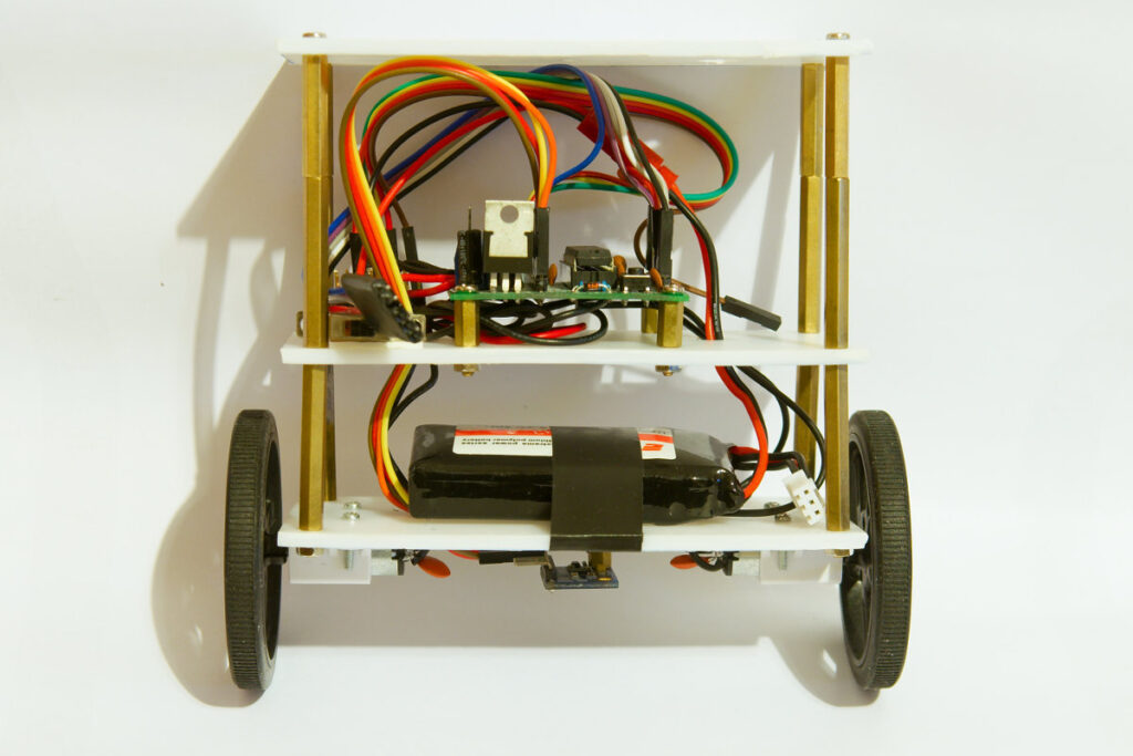
Self balancing bot
I bought most of the parts to built a self balancing bot many months ago. This time I didn’t use cheap Chinese stuff. I actually bought Pololu parts from a local shop. Pololu has a nice range of motors and motor controllers. I wanted to keep the bot small so I used the micro metal gear motors with 2 matching 60mm wheels. I did go for the most powerful version of the micro metal gear motors. To control the motors I got a DRV8833 break out board.
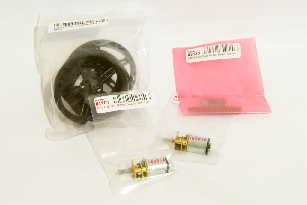
Pololu motors and wheels
For the electronics I used one of my own PCB creations, a Bajduino of course 🙂 It’s just a small (50x50mm) break out board for an ATmega328. I’m running the ATmega @ 16MHz and 3.3V. It’s out of spec according to the datasheet but it works… I also needed an IMU of course. I found a MP6050 sensor in my parts box. The MPU6050 combines a 3 DOF gyro and 3 DOF accelerometer in a small package, ideal for a self balancing bot.
The chassis is made from a sheet of polystyrene, I made 3 small plates out of a big sheet. Polystyrene is very easy to cut up with a sharp knife. Very handy to quickly make a custom robot chassis. I then drilled holes in the plates to fit the motors and electronics. To connect the 3 chassis plates I used brass spacers. I mounted the MPU6050 sensor to the bottom of the lowest chassis plate.
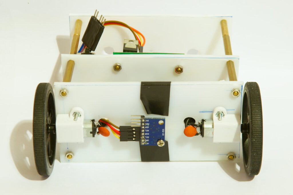
Self balancing bot
I did have some trouble with the little motors. During my initial tests I noticed that the MPU6050 sensor would stop working when driving the motors. I hooked up my oscilloscope to the 3.3V that powers the sensor and saw that the regulator on my board was oscillating.

LM1117 oscillating
Brushed DC motors are noisy things so I soldered the biggest (0,22µF) ceramic capacitors I had on hand to each motor. This did the trick and the regulator now gives a nice stable 3.3V.
The hard part in building a self balancing bot is coding it. Luckily there are some smart people that have shared their code and ideas about self balancers. So I just borrowed a lot of code I found online and turned it in to something that makes my bot balance.
First thing I needed was code to get the data from the MPU6050 sensor. You need some kind of filter to get good results. There are different ways of doing this. The guys from TKJElectronics have shared the necessary code to get the data from the MPU6050 sensor. They have also made a library for a Kalman filter. Their code can be downloaded on Github.
Next step was coding a PID algorithm. I have no experience with this and tried lots of different things. Including using the Arduino PID library. I could never get decent results with it so I gave up pretty fast. I then got some nice PID code from someone on letsmakerobots (thanks Protowrxs). This code worked a lot better but I could not find the right PID parameters. I then had a good look at this excellent guide to make a self balancing bot and rewrote my sketch. The following video shows my latest code:
This is the sketch I’m using (you need the library from TKJElectronics to compile this code):
// http://www.bajdi.com
// Self balancing bot:
// µController = ATmega328
// 2 Pololu micro metal gear motors with 60mm wheels + DRV8833 motor controller
// 6DOF MPU6050 sensor

#include <Wire.h>
#include "Kalman.h" // Source: https://github.com/TKJElectronics/KalmanFilter

Kalman kalmanX; // Create the Kalman instance

/* IMU Data */
int16_t accX, accY, accZ;
int16_t tempRaw;
int16_t gyroX, gyroY, gyroZ;

float accXangle;//, accYangle; // Angle calculate using the accelerometer
float gyroXangle;//, gyroYangle; // Angle calculate using the gyro
float kalAngleX;//, kalAngleY; // Calculate the angle using a Kalman filter

unsigned long timer;
uint8_t i2cData[14]; // Buffer for I2C data
float CurrentAngle;

// Motor controller pins
const int AIN1 = 3;  // (pwm) pin 3 connected to pin AIN1
const int AIN2 = 9;  // (pwm) pin 9 connected to pin AIN2
const int BIN1 = 10; // (pwm) pin 10 connected to pin BIN1
const int BIN2 = 11;  // (pwm) pin 11 connected to pin BIN2

int speed;

// PID
const float Kp = 4;
const float Ki = 1;
const float Kd = 1;
float pTerm, iTerm, dTerm, integrated_error, last_error, error;
const float K = 1.9*1.12;
#define   GUARD_GAIN   10.0

#define runEvery(t) for (static typeof(t) _lasttime;(typeof(t))((typeof(t))millis() - _lasttime) > (t);_lasttime += (t))


void setup() {
  pinMode(AIN1, OUTPUT); // set pins to output
  pinMode(AIN2, OUTPUT);
  pinMode(BIN1, OUTPUT);
  pinMode(BIN2, OUTPUT);
  Serial.begin(57600);
  Wire.begin();
  i2cData[0] = 7; // Set the sample rate to 1000Hz - 8kHz/(7+1) = 1000Hz
  i2cData[1] = 0x00; // Disable FSYNC and set 260 Hz Acc filtering, 256 Hz Gyro filtering, 8 KHz sampling
  i2cData[2] = 0x00; // Set Gyro Full Scale Range to ±250deg/s
  i2cData[3] = 0x00; // Set Accelerometer Full Scale Range to ±2g
  while(i2cWrite(0x19,i2cData,4,false)); // Write to all four registers at once
  while(i2cWrite(0x6B,0x01,true)); // PLL with X axis gyroscope reference and disable sleep mode

    while(i2cRead(0x75,i2cData,1));
  if(i2cData[0] != 0x68) { // Read "WHO_AM_I" register
    Serial.print(F("Error reading sensor"));
    while(1);
  }

  delay(100); // Wait for sensor to stabilize

  /* Set kalman and gyro starting angle */
  while(i2cRead(0x3B,i2cData,6));
  accX = ((i2cData[0] << 8) | i2cData[1]);
  accY = ((i2cData[2] << 8) | i2cData[3]);
  accZ = ((i2cData[4] << 8) | i2cData[5]);
  accXangle = (atan2(accY,accZ)+PI)*RAD_TO_DEG;

  kalmanX.setAngle(accXangle); // Set starting angle
  gyroXangle = accXangle;
  timer = micros();
}

void loop() {
  runEvery(25)  // run code @ 40 Hz
  {
    dof();
    if (CurrentAngle <= 180.2 && CurrentAngle >= 179.8)
    {
      stop();
    }
    else{
    if (CurrentAngle < 230 && CurrentAngle > 130)
    {
    Pid();
    Motors();
    }
    else
    {
      stop();
    }
  }
  }
}

void Motors(){
  if (speed > 0)
  {
    //forward
    analogWrite(AIN1, speed);
    analogWrite(AIN2, 0);
    analogWrite(BIN1, speed);
    analogWrite(BIN2, 0);
  }
  else
  {
    // backward
    speed = map(speed,0,-255,0,255);
    analogWrite(AIN1, 0);
    analogWrite(AIN2, speed);
    analogWrite(BIN1, 0);
    analogWrite(BIN2, speed);
  }
}

void stop()
{
  analogWrite(AIN1, 0);
  analogWrite(AIN2, 0);
  analogWrite(BIN1, 0);
  analogWrite(BIN2, 0);
}

void Pid(){
  error = 180 - CurrentAngle;  // 180 = level
  pTerm = Kp * error;
  integrated_error += error;
  iTerm = Ki * constrain(integrated_error, -GUARD_GAIN, GUARD_GAIN);
  dTerm = Kd * (error - last_error);
  last_error = error;
  speed = constrain(K*(pTerm + iTerm + dTerm), -255, 255);
}

void dof()
{
  while(i2cRead(0x3B,i2cData,14));
  accX = ((i2cData[0] << 8) | i2cData[1]);
  accY = ((i2cData[2] << 8) | i2cData[3]);
  accZ = ((i2cData[4] << 8) | i2cData[5]);
  tempRaw = ((i2cData[6] << 8) | i2cData[7]);
  gyroX = ((i2cData[8] << 8) | i2cData[9]);
  gyroY = ((i2cData[10] << 8) | i2cData[11]);
  gyroZ = ((i2cData[12] << 8) | i2cData[13]);
  accXangle = (atan2(accY,accZ)+PI)*RAD_TO_DEG;
  double gyroXrate = (double)gyroX/131.0;
  CurrentAngle = kalmanX.getAngle(accXangle, gyroXrate, (double)(micros()-timer)/1000000);
  timer = micros();
}
I spent hours trying to find the right PID parameters but the bot still does not balance like it should… I tried lots of things, to no avail. I changed the height of the bot. Moved the battery from the top to the bottom… I’m giving up for the moment. I might take another shot at it at a later date.