By Bajdi on July 8, 2012
Arduino rc car from Bajdi on Vimeo.
I finally made my old Nikko RC car work again 🙂 It wasn’t easy to be honest, there were several obstacles along the way. Since my last post I had found out that the L298 H-bridge was not powerful enough to drive the motor. It would quickly heat up and then turn it’s self of. The L298 has 2 channels and it’s possible to pair them, this should be good for 4A. How to connect the pins from the 2 channels is explained in the L298 datasheet. I soldered some wires to the bottom of my L298 board to pair the 2 channels.
To power the L298, Arduino and servo I first used a 2 cell Lipo battery. The voltage of the Lipo is to high for the little SG90 servo so I used a 3A UBEC to drop the voltage to 5V. I hooked up a small nRF24L01 module to the Arduino sensor shield for the wireless control. I quickly came to the conclusion that this wasn’t going to work. Every time I tried to move the rc car forward or backward the Arduino would reset. The Lipo battery is certainly powerful enough so it must be “electrical noise” from the motor that caused the Arduino to reset. I then soldered the biggest non polarized cap I found in my parts box to the motor terminals but to no avail. The simplest solution was to add another battery, so I powered the Arduino from a 9V battery.
Then my nRF24L01 modules started dropping packets when I turned the front wheels. Caused by noise from the UBEC. So I taped the nRF24L01 module to the old antenna on the rc car so there was some room between the UBEC and the wireless module. And then I was able to play with my old rc car again 🙂 I used my self made remote control with the same sketch I use for my Rover 5. This sketch just sends the analog readings of the joystick to the RC car. I just put all the parts on the chassis and put some tape around it. It’s far from an elegant solution but it works…
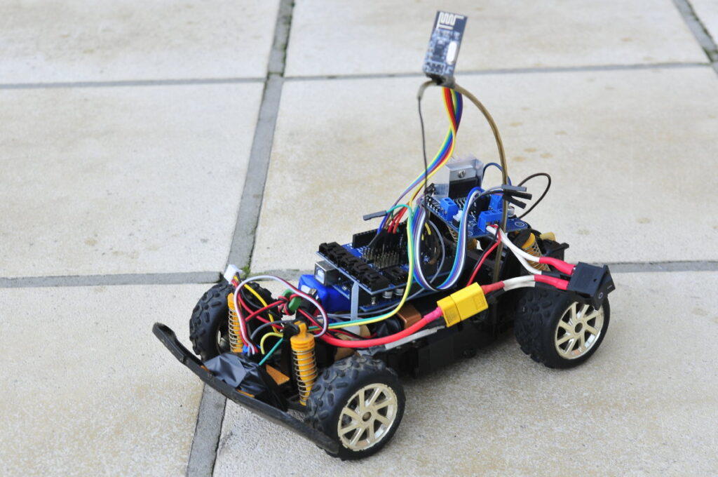
Arduino rc car
Posted in Arduino | Tagged L298, nRF24L01 |
By Bajdi on June 29, 2012
My line following robot from Bajdi on Vimeo.
A couple of months ago I started building a line following robot, I named it Volga 🙂 The plan was to draw a small track and plot it out on a large piece of paper and make a robot that could follow the track. In this case the plan was successful as tonight my little robot has been doing some laps around my test track without needing my intervention. I’m pleased with the result 🙂
Because I designed a special PCB for this simple robot it took me so long to finish it. Volga is controlled by an Arduino Nano plugged on my “Nano undershield”. Volga has 2 continuous rotation servos and the line following sensor is made up of 5 TCRT5000 sensors. I originally started with 3 TCRT5000 sensors. This worked but sometimes the robot would run of the track at 90° corners. I originally started programming the line following code on my own using lots of if functions. You can see a small video of my results with 3 sensors here.
Chris from Rocket brand studios then gave me a link to an Arduino sketch with some line following code in it. His code uses 5 sensors so I decided to add 2 more TCRT5000 line sensors. I had a good look at the sketch and adapted it to my robot, the result you can see in the above video. The robot is a bit spastic as it changes direction but it keeps following the black line pretty well.
This robot is easy to replicate and not so hard to code, line following is actually pretty straight forward to program. The whole robot was made and programmed in only a couple of hours, spread out over 3 months 🙂 It’s also a cheap project. The chassis is a plastic box I found, I bought the 2 continuous rotation servos and wheels on Ebay for a very reasonable price. I’m especially proud on my self designed Nano Undershield and the line following sensor board which I also made myself. The TCRT5000 sensors can be found on Ebay for only a couple of dollars or you can by them from Yourduino if you prefer a webshop.
Here is the sketch I used in the top video:
// Volga: the cheap and simple line following robot
// http://www.bajdi.com
// With the help from Chris @ http://rocketbrandstudios.com/
// 2 continuous rotation servos
// 5 TCRT5000 sensors connected to analog inputs = line following sensor

#include <Servo.h>

Servo leftservo;  // create servo object to control a servo
Servo rightservo; // create servo object to control a servo
int rawtcrt[5];   //these are the raw ADC values from the line follow sensor
/*
rawtcrt[0] = left sensor
 rawtcrt[1] = left middle sensor
 rawtcrt[2] = middle sensor
 rawtcrt[3] = right middle sensor
 rawtcrt[4] = right sensor
 */
int bwtcrt[5];  //these are basically booleans we will use 0 for white and 1 for black
int i;
int colorThreshold = 400; // < 400 = white / > 400 = black


void setup()

{

  leftservo.attach(2);   // attaches the servo on pin 2 to the servo object
  leftservo.write(90);   // stop servo
  rightservo.attach(3);  // attaches the servo on pin 3 to the servo object
  rightservo.write(90);  // stop servo

}

void loop()
{
  checkLineSensor(); //1 = seeing black    0 = seeing white
  forward();
  if (bwtcrt[1]==1)
  {
    forwardleft();
  }
  if (bwtcrt[3]==1)
  {
    forwardright();
  }
  if (bwtcrt[4]==1)
  {
    right();
  }
  if (bwtcrt[0]==1)
  {
    left();
  }
}

void checkLineSensor()
{
  for (i=0;i<5;i++)
  {
    rawtcrt[i]=analogRead(i);
    if (rawtcrt[i]<colorThreshold)
    {
      bwtcrt[i]=0;
    }
    else{
      bwtcrt[i]=1;
    }
  }
}

void forward(){
  leftservo.write(70);              // go straight forward
  rightservo.write(110);
}

void forwardleft(){
  leftservo.write(85);              // go forward left
  rightservo.write(102);
}

void forwardright(){
  leftservo.write(78);              // go forward right
  rightservo.write(95);
}

void left(){
  leftservo.write(110);                // go left
  rightservo.write(110);
}

void right(){
  leftservo.write(70);              // go right
  rightservo.write(70);
}
Posted in Arduino sketches, Line following robot | Tagged Nano, robot, TCRT5000 |
By Bajdi on June 24, 2012
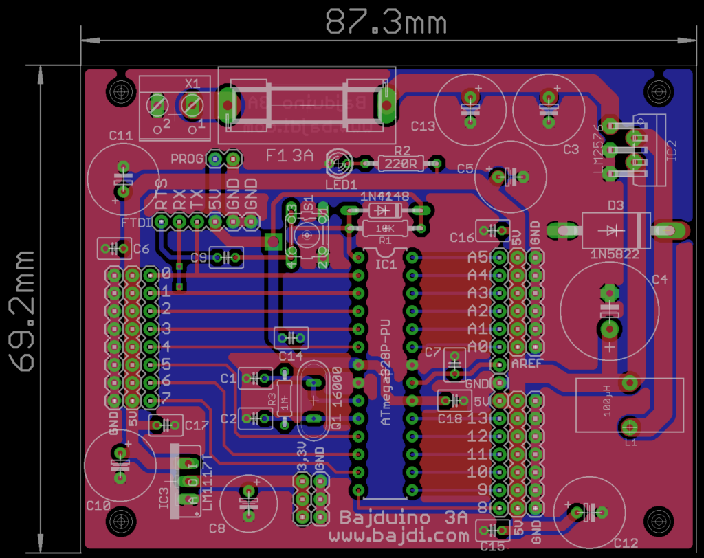
Bajduino 3A: ATmega 328P-PU powered by LM2576 5V 3A regulator. 3 rows of male headers for easy connection of servos and sensors.
After successfully designing and soldering my first PCB it’s time to take things a little further and design my own Arduino, the Bajduino :p. I’ve bought all the necessary electronic components to make a lot of boards. So now I only need to finish my PCB designs and have them made by Seeedstudio or Iteadstudio in China. These are the cheapest PCB services I know of, they seem to be very popular and I have read good reviews of both of them. After I found out that the Chinese PCB manufacturers charge the same price for a single and dual layer PCB I changed all my designs to dual layer PCB’s. I’ve also added ground planes to the top and bottom of the boards.
The next PCB I’ll have made is my Bajduino 3A. It is based on the ATmega 328P-PU micro controller and the LM2576 3A 5V switch mode regulator. I hope to use this board for a small hexapod that I will built in the future. The 3A 5V regulator should be powerful enough to power the servos as I have proven in the video in my previous post. I’ve spent a considerable amount of time on this board and learned a lot of things. I’ve spent hours reading the datasheets of the various components, especially the datasheets of the ATmega 328 and the LM2576 regulator. It’s also a good idea to study the design of the official Arduino boards. There were a couple of things that I had overlooked in my first design. Things like the 1 mega ohm resistor across the crystal and the reverse biased diode across the 10K pullup resistor on the reset line. There are a massive amount of capacitors on the board. But since the board will be used to power 12 servos the caps will help filter the noise and prevent voltage surges. The cheap micro 9G servos that I’ve already bought are noisy things. Tayda electronics has already supplied me with a couple of hundred capacitors.
The 5V trace is very wide so that it can handle the current drawn by the servos. There is an FTDI header on the board, as I’ll use an FTDI to TTL cable that I have bought on Ebay to upload sketches and for using the Arduino serial monitor. The prog jumper on the top left of the board will be removed when using the FTDI cable, else the board and all the things connected to it would be powered by the USB cable. Not something you want to try when there are 12 servos connected to the board. The 3,3V regulator in the bottom left corner will be used to power a nRF24L01 module so I can remote control my hexapod. For safety reasons I have added a fuse on the input as I will use a Lipo battery to power the board. You just need to search on Youtube for exploding Lipos to know why it’s a very good idea. These batteries don’t like short circuits.
I’ve used Eagle 6.2.0 for all my designs. It took me some time to figure out all the features and I still have a lot to learn. To check my designs before sending them out I’ve installed Gerbv, an open source Gerber viewer. It’s best to thoroughly check your design in a Gerber viewer before sending out the Gerber files to the PCB manufacturer.
I’m already working on my next PCB, a simple breakout board for the ATmega 1284P-PU. This is a 40 pin micro controller with 128kb of memory. The biggest micro controller Atmel makes in DIP format.
Posted in Arduino | Tagged ATmega328P-PU, Bajduino |