By Bajdi on December 8, 2012
The first type of robot most people make is an obstacle avoiding robot. You take a couple of motors with a motor controller, an ultrasonic or infrared range finder sensor and add a micro controller and you have a simple robot. I have made a couple of these robots myself.
This time I wanted to try something different. Why not let the robot bump in to things and then try and detect “the crash”? The simplest way to detect that the robot has bumped in to something is to use a couple of simple bumper switches. You can easily make them yourself with some metal wire. But in this digital age why not use a digital sensor?
A sensor that can detect crashes is for example an accelerometer. Accelerometers sense movement so it can detect if the robot has crashed in to something. I bought an ADXL345 accelerometer a long time ago. I never did anything really useful with it. So it was time to put it to work.
The ADXL345 is a 3-axis accelerometer, it works at 3.3V and uses the I2C or SPI bus to communicate with a micro controller. These sensors are quite complex to get data from, well if your not a programming wizard… I found a library and example sketch on the bildr blog to get me started. This library makes it possible to use all the features of the ADXL345 accelerometer, including the tap detection. The tap detection can be used to sense if the robot has crashed.
The library makes it very easy to use that feature. I just copied the example sketch and deleted the stuff that I didn’t need. I then added the code needed to control the motors and that was it. I programmed it so that when the robot crashes it first drives backward and then turns right. I’m starting to get the hang of this. I made the following sketch in less then an hour 🙂
/* http://www.bajdi.com (your number one source for buggy Arduino sketches)
 Crash robot
 Micro controller = ATmega1284P-PU with Maniacbugs Arduino bootloader https://github.com/maniacbug/mighty-1284p
 Using a L293D (bought from my favorite Ebay seller Polida) to drive 2 yellow "Ebay motors with yellow wheels"
 Detecting crashes with an ADXL345 accelerometer, used library from http://bildr.org/2011/03/adxl345-arduino/
 */
#include
#include

// motor stuff
const int EN1 = 3;        //enable motor 1 = pin 1 of L293D
const int direction1 = 2; //direcion motor 1 = pin 2 of L293D
const int EN2 = 4;        //enable motor 2 = pin 9 of L293D
const int direction2 = 5; //direction motor 2 = pin 15 of L293D
int speedLeft = 205; //there seems to be a bit of a difference between these cheap motors :(
int speedRight = 255; //this motor needs a bit more voltage to keep up with the other
//**********************


int led = 0;      // a led on pin 0
boolean crashed = false;
unsigned long timer;
int backwardTime = 1000;
int turnRightTime = 1000;


ADXL345 adxl; //variable adxl is an instance of the ADXL345 library

void setup(){
  Serial.begin(9600);
  pinMode(led, OUTPUT);

  // motor stuff
  pinMode(EN1, OUTPUT);
  pinMode(direction1, OUTPUT);
  pinMode(EN2, OUTPUT);
  pinMode(direction2, OUTPUT);
  analogWrite(EN1, 0);
  analogWrite(EN2, 0);
  //***************

  // ADXL345 things
  adxl.powerOn();
  adxl.setTapDetectionOnX(1);
  adxl.setTapDetectionOnY(1);
  adxl.setTapDetectionOnZ(1);
  adxl.setTapThreshold(100); //62.5mg per increment
  adxl.setTapDuration(5); //625μs per increment
  adxl.setInterruptMapping( ADXL345_INT_SINGLE_TAP_BIT,   ADXL345_INT1_PIN );
  adxl.setInterrupt( ADXL345_INT_SINGLE_TAP_BIT, 1);
  //***************
}

void loop(){

  // ADXL345 tap detection
  byte interrupts = adxl.getInterruptSource();
  if(adxl.triggered(interrupts, ADXL345_SINGLE_TAP))
  {
    Serial.println("tap");
    crashed = true;
    timer = millis();
  }

  if (crashed == true)  // we have crashed
  {
    if (millis() - timer <= backwardTime ) // lets backup
    {
      backward();
      digitalWrite(led, HIGH);
    }
    if (millis() - timer > backwardTime && millis() - timer < backwardTime + turnRightTime) // lets turn right
    {
      right();
      digitalWrite(led, HIGH);
    }
    if (millis() - timer == backwardTime + turnRightTime)  // enough of this
    {
      crashed = false;
    }
  }
  if (crashed == false)  // full steam ahead
  {
    forward();
    digitalWrite(led, LOW);
  }
}

void forward()
{
  digitalWrite(direction1, HIGH);
  digitalWrite(direction2, HIGH);
  analogWrite(EN1, speedLeft);
  analogWrite(EN2, speedRight);
}

void backward()
{
  digitalWrite(direction1, LOW);
  digitalWrite(direction2, LOW);
  analogWrite(EN1, speedLeft+35);
  analogWrite(EN2, speedRight-15);
}

void right()
{
  digitalWrite(direction1, HIGH);
  digitalWrite(direction2, LOW);
  analogWrite(EN1, speedLeft);
  analogWrite(EN2, speedRight-30);
}
For this robot I used one of my self designed boards, the Bajduino Mega 3A with an ATmega1284P-PU micro controller to control the robot. It’s the biggest board I have designed so far. It has a 3A 5V switch mode regulator, a linear 3.3V regulator (LD1117-3.3) and a logic level converter with the appropriate pull-up resistors. Since the ADXL345 works at 3.3V and the ATmega1284 I2C bus is 5V it’s best to do some level shifting. You can get away with just some pull up resistors to 3.3V. I’ve done that when I first tried out the ADXL345, but it’s recommended to use a logic level converter.
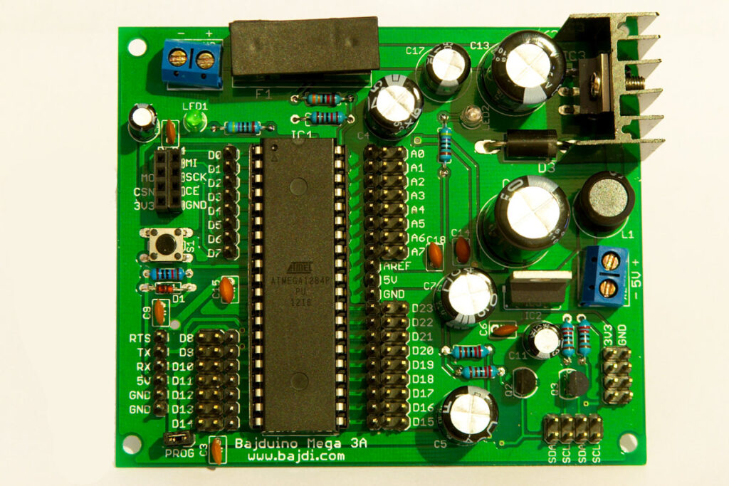
Bajduino mega 3A
Posted in Arduino sketches | Tagged ADXL345, ATmega1284, robot |
By Bajdi on November 30, 2012
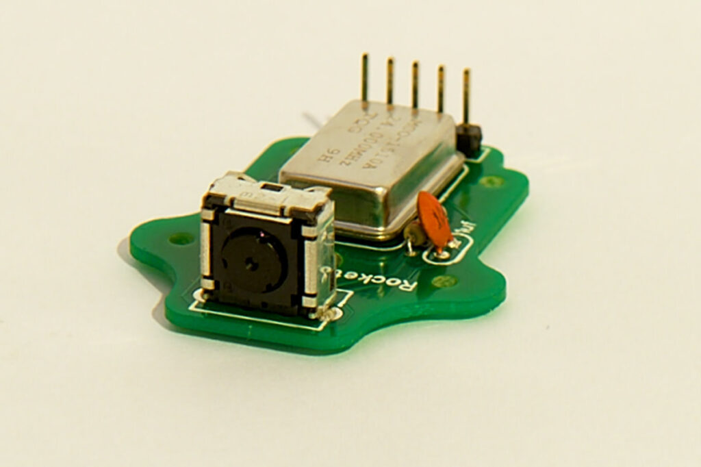
WiiCamera sensor
I spent to much time on LetsMakeRobots. LMR not only has project pages and a forum about robots but it also has a shoutbox. It’s a place where robot builders of all ages and locations come together to talk about robots and electronics. One of the people I have met on the shoutbox is “Chris the carpenter”. He is the man behind Rocket brand studios, a small online shop that sells robots and parts for robots.
While browsing the Rocket brand studios website I came across the WiiCamera sensor. I found a really cool video that demonstrated the WiiCamera and just had to have one, so I ordered 2 🙂
The WiiCamera is a tiny IR camera that comes out of a WiiMote. The camera has an I2C interface and can see up to 4 IR light sources. For every IR light source the camera outputs an X/Y position, size and brightness. Rocket brand studios sells the sensor on a PCB with the necessary components to make it work. To Hook it up to an Arduino you connect the camera to 3V3, 5V and SDA/SCL for the I2C connections.
Reading data from the sensor is easy because Stephen Hobley has written the PVision library for the WiiCamera. It comes with an example sketch, reading data from the sensor is very straight forward. It took me only a couple of minutes to make it work. I then mounted the sensor on a pan/tilt bracket with 2 small servos. The sensor comes with the original IR shield of the WiiMote. It’s a little plastic thing, I mounted it in front of the sensor else I had some interference with the fluorescent lights in my room. And then I started writing a sketch to track an IR led with the WiiCamera…
After a big struggle I came up with a sketch so that the WiiCamera tracks an IR light source pretty accurately. Next step is to integrate this code in the sketch of one of my robots. You can do all sorts of fun things with it. Let one robot follow another, or hold a candle/IR led in front of the robot and let it follow you while you walk around.
I find it pretty strange that this sensor doesn’t get more attention. It works very well and can be used for lots of cool things. It is not cheap though @ 35$, but I think it’s well worth it’s price. You can get the sensor cheaper if you can find a broken WiiMote with a working sensor. You can harvest the sensor out of the broken WiiMote and make your own PCB to mount it on.
This is the sketch I used in the video:
// http://wwww.bajdi.com
// WiiCamera tracking IR light source (IR led, lighter, candle)
// WiiCamera mounted on pan/tilt kit, 2 SG90 servos

// WiiCamera data:
// blob X = 0 IR source on the right
// blob X = 1024 IR source on the left
// blob Y = 0 IR source top
// blob Y = 1024 IR source bottom

#include <Servo.h>
#include <Wire.h>
#include <PVision.h>

Servo panServo;
Servo tiltServo;
PVision ircam;

int panServoLeft = 2000;
int panServoCenter = 1380;
int panServoRight = 600;
int panServoPos;
int tiltServoUp = 650;
int tiltServoCenter = 1250;
int tiltServoDown = 1800;
int tiltServoPos;

byte result;

#define runEvery(t) for (static typeof(t) _lasttime;(typeof(t))((typeof(t))millis() - _lasttime) > (t);_lasttime += (t))

void setup()
{
  ircam.init();
  delay(50);
  panServo.attach(46);
  panServoPos = panServoCenter;
  panServo.writeMicroseconds(panServoPos);
  tiltServo.attach(47);
  tiltServoPos = tiltServoCenter;
  tiltServo.writeMicroseconds(tiltServoPos);
  delay(500);
}

void loop()
{
  runEvery(20)
  {
    result = ircam.read();      // get the results from the ircam
    if (result & BLOB1)        // IR detected
    {
      if (ircam.Blob1.X < 450 && panServoPos > panServoRight)
      {
        panServoPos -= 10;
      }
      if (ircam.Blob1.X > 550 && panServoPos < panServoLeft)
      {
        panServoPos += 10;
      }
      if (ircam.Blob1.X <= 550 && ircam.Blob1.X >= 500) // IR light close to center
      {
        panServoPos += 1;
      }
      if (ircam.Blob1.X < 500 && ircam.Blob1.X >= 450) // IR light close to center
      {
        panServoPos -= 1;
      }

      if (ircam.Blob1.Y < 450 && tiltServoPos > tiltServoUp)
      {
        tiltServoPos -= 10;
      }
      if (ircam.Blob1.Y > 550 && tiltServoPos < tiltServoDown)
      {
        tiltServoPos += 10;
      }
      if (ircam.Blob1.Y <= 550 && ircam.Blob1.Y >= 500) // IR light close to center
      {
        tiltServoPos += 1;
      }
      if (ircam.Blob1.Y < 500 && ircam.Blob1.Y >= 450) // IR light close to center
      {
        tiltServoPos -= 1;
      }
    }

    else {      // no IR detected = center the servos

      if (panServoPos > panServoCenter) // center pan servo
      {
        panServoPos -= 10;
      }
      if (panServoPos < panServoCenter)  // center pan servo
      {
        panServoPos += 10;
      }
      if (tiltServoPos > tiltServoCenter) // center tilt servo
      {
        tiltServoPos -= 10;
      }
      if (tiltServoPos < tiltServoCenter) // center tilt servo
      {
        tiltServoPos += 10;
      }
    }
    panServo.writeMicroseconds(panServoPos);
    tiltServo.writeMicroseconds(tiltServoPos);
  }
}
Posted in Arduino sketches | Tagged WiiCamera |
By Bajdi on November 23, 2012
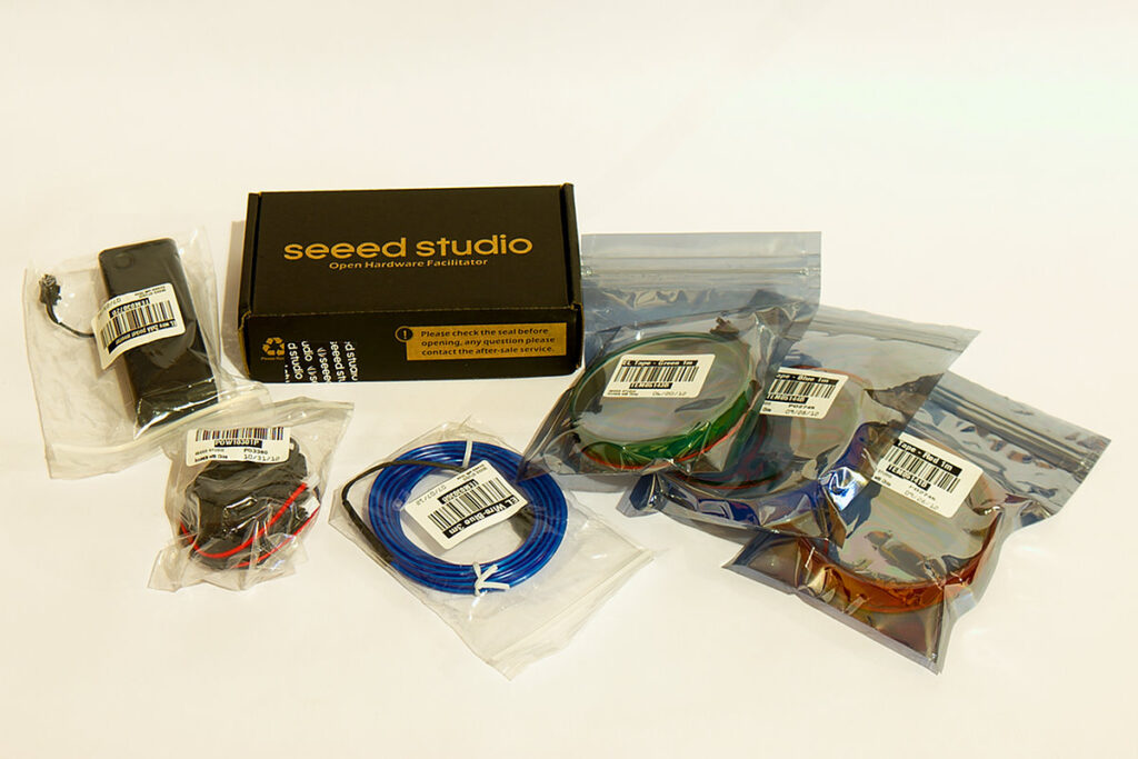
Seeedstudio EL shield
Beginning of this month I entered Seeedstudios give-away, and I won an EL-shield 🙂 You can find more information about the give-away on the Seeedstudio blog. I received the package this week only 2 weeks after it had been shipped. Not bad for a package that was sent all the way from China to Belgium.
This is the EL-shield:
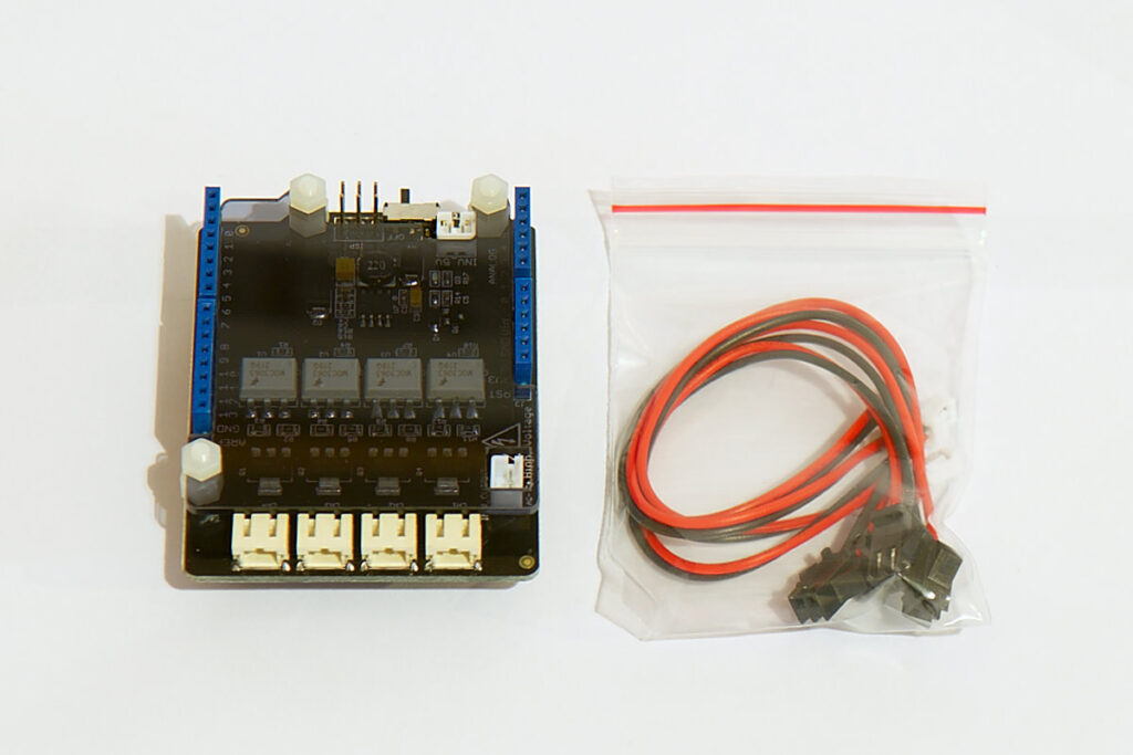
Seeedstudio EL shield
It is of course compatible with the Arduino Duemilanove/Uno/Mega boards. The shield comes with 4 wires, one end connects to the shield and the other end goes to the EL-wire or EL-tape.
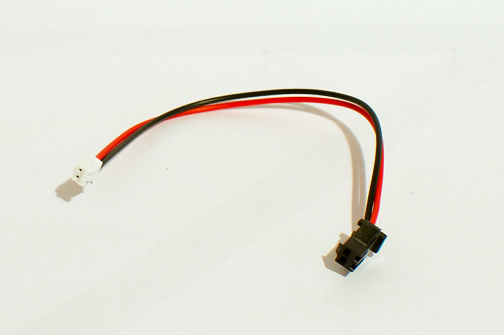
EL connector
El wire is an electroluminescent wire that glows when you connect it to an AC voltage. The Arduino works with DC voltage so you need an inverter to convert the 5V of the Arduino to 110V AC. The EL shield does not include an inverter, you need to buy it separately. Seeedstudio sells a robust EL inverter that comes with the right connectors to hook up to the shield. The connector with the red and black wire is the input (5V) of the inverter, the connector with the black wires is the output.
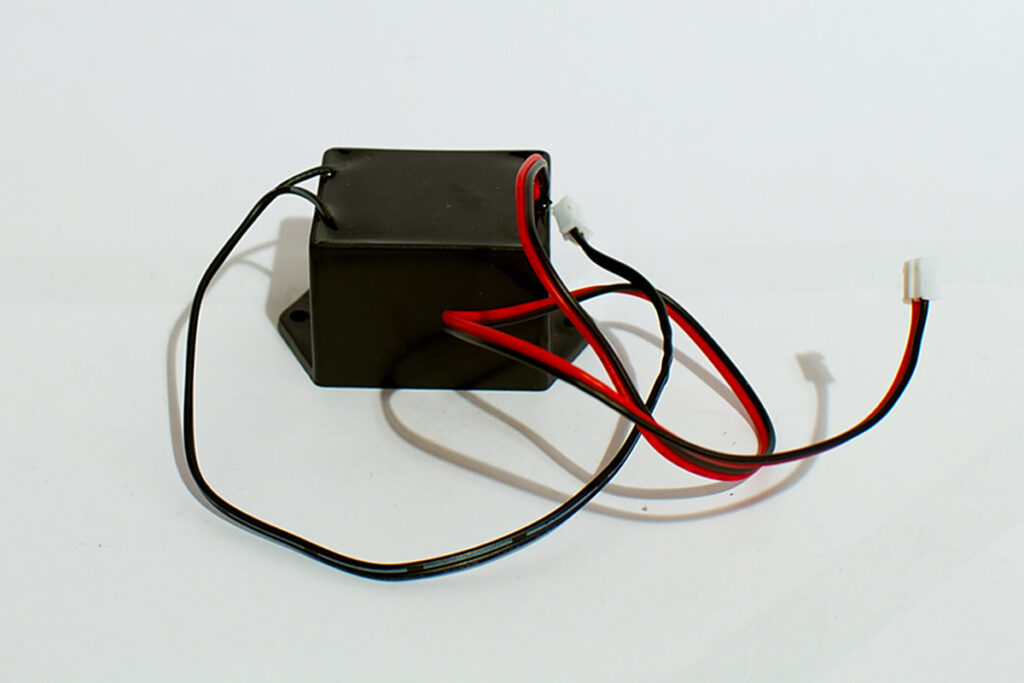
EL inverter
To test the shield I plugged it on an Arduino Duemilanove and connected the inverter and some EL wire and EL tape. Seeedstudio has made a wiki page of the shield where you can find a simple sketch to test it. So I uploaded that sketch to the Arduino. Here is a video of the result:
The El shield has 4 connectors to connect EL wire or tape. These connectors can be controlled by writing the pins 4,5,6 and 7 of the Arduino high or low. El wire can not be dimmed with the EL shield, only turned on or of. Dimming EL wire is not so simple you would need to change the frequency/voltage of the inverter. The inverter makes a high pitched sound, this is normal for these high frequency electronics. Another downside of these inverters is that they generate lots of electrical noise. The 5V input of the inverter is fed from a switch mode regulator on the EL shield, it takes it input from the Vin pin or power jack of the Arduino. That way the 5V regulator on the Arduino isn’t overloaded. I have measured the current the inverter draws with 6 meter of EL wire and tape attached to the output and the inverter was drawing 700mA. When you power the Arduino through the USB connector the regulator on the EL shield is not used so the inverter gets 5V directly from USB. I would not recommend connecting lots of EL wire to the shield when you power the Arduino from USB, USB ports can only give 500mA. I hooked up my oscilloscope to the 5V of the Arduino when powering it from USB and the 5V line immediately dropped below 4V with lots of noise. So I strongly recommend to not power the Arduino from USB when using the shield with lots of EL wire. Use a strong battery and connect it to the power jack or Vin pin of the Arduino instead. In the video I used a 2S Lipo battery connected to the power jack using my Lipo to Arduino cable.
My conclusion:
The EL shield is the easiest way to control EL wire or tape with an Arduino. The shield is very well made, the high voltage electronics are nicely shielded of with a thick piece of acrylic. When powering the Arduino/EL shield through the power jack the shield generates 5V for the inverter through its own voltage regulator so you don’t need to worry about blowing up your Arduino. The shield and inverter are capable of driving 15 meter of EL wire or tape, that’s a lot :p
I have been working on my hexapod the last couple weeks. So I thought it would be a good idea to add some EL wire to my hexapod. I strapped 3 meters of blue EL wire around it. I programmed it so that I can turn on and of the EL wire with a button on my remote. I’ve made a video of it 😀
Posted in Arduino | Tagged EL shield |