The first type of robot most people make is an obstacle avoiding robot. You take a couple of motors with a motor controller, an ultrasonic or infrared range finder sensor and add a micro controller and you have a simple robot. I have made a couple of these robots myself.
This time I wanted to try something different. Why not let the robot bump in to things and then try and detect “the crash”? The simplest way to detect that the robot has bumped in to something is to use a couple of simple bumper switches. You can easily make them yourself with some metal wire. But in this digital age why not use a digital sensor?
A sensor that can detect crashes is for example an accelerometer. Accelerometers sense movement so it can detect if the robot has crashed in to something. I bought an ADXL345 accelerometer a long time ago. I never did anything really useful with it. So it was time to put it to work.
The ADXL345 is a 3-axis accelerometer, it works at 3.3V and uses the I2C or SPI bus to communicate with a micro controller. These sensors are quite complex to get data from, well if your not a programming wizard… I found a library and example sketch on the bildr blog to get me started. This library makes it possible to use all the features of the ADXL345 accelerometer, including the tap detection. The tap detection can be used to sense if the robot has crashed.
The library makes it very easy to use that feature. I just copied the example sketch and deleted the stuff that I didn’t need. I then added the code needed to control the motors and that was it. I programmed it so that when the robot crashes it first drives backward and then turns right. I’m starting to get the hang of this. I made the following sketch in less then an hour 🙂
/* http://www.bajdi.com (your number one source for buggy Arduino sketches)
 Crash robot
 Micro controller = ATmega1284P-PU with Maniacbugs Arduino bootloader https://github.com/maniacbug/mighty-1284p
 Using a L293D (bought from my favorite Ebay seller Polida) to drive 2 yellow "Ebay motors with yellow wheels"
 Detecting crashes with an ADXL345 accelerometer, used library from http://bildr.org/2011/03/adxl345-arduino/
 */
#include
#include

// motor stuff
const int EN1 = 3;        //enable motor 1 = pin 1 of L293D
const int direction1 = 2; //direcion motor 1 = pin 2 of L293D
const int EN2 = 4;        //enable motor 2 = pin 9 of L293D
const int direction2 = 5; //direction motor 2 = pin 15 of L293D
int speedLeft = 205; //there seems to be a bit of a difference between these cheap motors :(
int speedRight = 255; //this motor needs a bit more voltage to keep up with the other
//**********************


int led = 0;      // a led on pin 0
boolean crashed = false;
unsigned long timer;
int backwardTime = 1000;
int turnRightTime = 1000;


ADXL345 adxl; //variable adxl is an instance of the ADXL345 library

void setup(){
  Serial.begin(9600);
  pinMode(led, OUTPUT);

  // motor stuff
  pinMode(EN1, OUTPUT);
  pinMode(direction1, OUTPUT);
  pinMode(EN2, OUTPUT);
  pinMode(direction2, OUTPUT);
  analogWrite(EN1, 0);
  analogWrite(EN2, 0);
  //***************

  // ADXL345 things
  adxl.powerOn();
  adxl.setTapDetectionOnX(1);
  adxl.setTapDetectionOnY(1);
  adxl.setTapDetectionOnZ(1);
  adxl.setTapThreshold(100); //62.5mg per increment
  adxl.setTapDuration(5); //625μs per increment
  adxl.setInterruptMapping( ADXL345_INT_SINGLE_TAP_BIT,   ADXL345_INT1_PIN );
  adxl.setInterrupt( ADXL345_INT_SINGLE_TAP_BIT, 1);
  //***************
}

void loop(){

  // ADXL345 tap detection
  byte interrupts = adxl.getInterruptSource();
  if(adxl.triggered(interrupts, ADXL345_SINGLE_TAP))
  {
    Serial.println("tap");
    crashed = true;
    timer = millis();
  }

  if (crashed == true)  // we have crashed
  {
    if (millis() - timer <= backwardTime ) // lets backup
    {
      backward();
      digitalWrite(led, HIGH);
    }
    if (millis() - timer > backwardTime && millis() - timer < backwardTime + turnRightTime) // lets turn right
    {
      right();
      digitalWrite(led, HIGH);
    }
    if (millis() - timer == backwardTime + turnRightTime)  // enough of this
    {
      crashed = false;
    }
  }
  if (crashed == false)  // full steam ahead
  {
    forward();
    digitalWrite(led, LOW);
  }
}

void forward()
{
  digitalWrite(direction1, HIGH);
  digitalWrite(direction2, HIGH);
  analogWrite(EN1, speedLeft);
  analogWrite(EN2, speedRight);
}

void backward()
{
  digitalWrite(direction1, LOW);
  digitalWrite(direction2, LOW);
  analogWrite(EN1, speedLeft+35);
  analogWrite(EN2, speedRight-15);
}

void right()
{
  digitalWrite(direction1, HIGH);
  digitalWrite(direction2, LOW);
  analogWrite(EN1, speedLeft);
  analogWrite(EN2, speedRight-30);
}
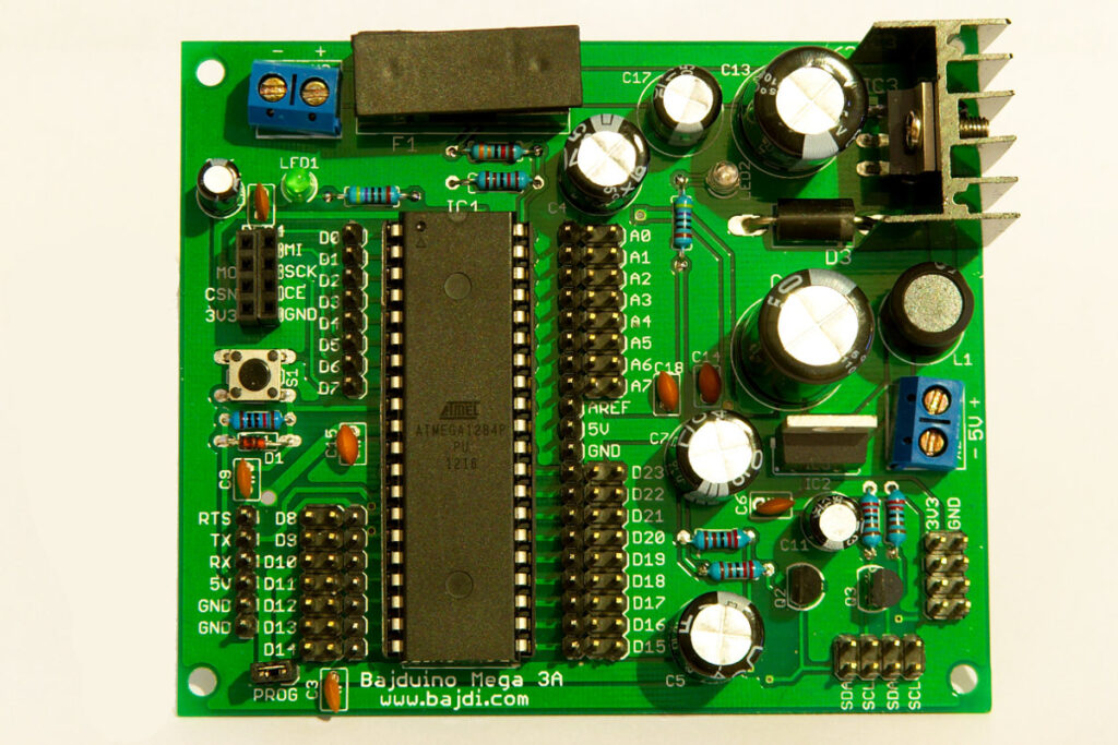
For this robot I used one of my self designed boards, the Bajduino Mega 3A with an ATmega1284P-PU micro controller to control the robot. It’s the biggest board I have designed so far. It has a 3A 5V switch mode regulator, a linear 3.3V regulator (LD1117-3.3) and a logic level converter with the appropriate pull-up resistors. Since the ADXL345 works at 3.3V and the ATmega1284 I2C bus is 5V it’s best to do some level shifting. You can get away with just some pull up resistors to 3.3V. I’ve done that when I first tried out the ADXL345, but it’s recommended to use a logic level converter.

Bajduino mega 3A