Bajdi electronics

Hobby electronics website

Browse: Page 13

Blinking leds with a 74HC595 shift register

By Bajdi on April 13, 2013

I needed to take a break from working on my hexapod. So I decided to go back to basics, blinking leds 😀 The first Arduino sketch most people try out must be the blink example sketch. It blinks one led, and uses only one pin. If you want to blink lots of leds you might run out of pins. You could of course use an Arduino Mega which has a lot of pins. But there are cheaper options. Like the 74HC595 shift register. I bought a dozen from Tayda Electronics, they only cost $0.20 a piece. The 74HC595 is an 8-bit serial-in, serial or parallel-out shift register with output latches.
That description sounds very complex. But a lot of information can be found on the internet about interfacing the 74HC595 with Arduino. The chip needs only needs 3 pins, in return you get 8 outputs. I tried some different sketches that I found online to try and understand how the chip works. The following sites I found the most useful:
Adafruit lesson on the 74HC595
Bildr 74HC595 tutorial
Arduino shiftout function

My goal was to blink 16 leds nightrider style. I used 2 74HC595 shift registers and 16 leds with 220ohm resistors. As I wanted to integrate the code in an other sketch I used the millis function to time the shifting of the leds. This is the result:

This is the code I used:

// http://www.bajdi.com
// Nightrider effect using 16 leds and 2 74HC595 shift registers

//Pin connected to Pin 12 of 74HC595 (Latch)
int latchPin = 8;
//Pin connected to Pin 11 of 74HC595 (Clock)
int clockPin = 12;
//Pin connected to Pin 14 of 74HC595 (Data)
int dataPin = 11;
//data for LED on. Second shift register will be written first.
int ledOn2[]={
  1,2,4,8,16,32,64,128,0,0,0,0, 0, 0, 0,  0, 0, 0, 0,0,0,0,0,128,64,32,16,8,4,2,1};
int ledOn1[]={
  0,0,0,0, 0, 0, 0,  0,1,2,4,8,16,32,64,128,64,32,16,8,4,2,1,  0, 0, 0, 0,0,0,0,0};
byte nextLed;
unsigned long Timer;

void setup() 
{
  pinMode(latchPin, OUTPUT);
  pinMode(clockPin, OUTPUT);
  pinMode(dataPin, OUTPUT);
}

void loop() 
{
  unsigned long ledMillis = millis();

  if (ledMillis >= Timer){
    Timer = Timer+50;
    nextLed = nextLed +1;
    digitalWrite(latchPin, LOW);
    shiftOut(ledOn2[nextLed]);
    shiftOut(ledOn1[nextLed]);
    //set latchPin to high to lock and send data
    digitalWrite(latchPin, HIGH);

    if (nextLed == 30){ 
      nextLed = 0;
    }
  }
}

void shiftOut(byte dataOut) 
{
  // Shift out 8 bits LSB first,
  // on rising edge of clock
  boolean pinState;
  //clear shift register ready for sending data
  digitalWrite(dataPin, LOW);
  digitalWrite(clockPin, LOW);
  // for each bit in dataOut send out a bit
  for (int i=0; i<=7; i++) 
  {
    //set clockPin to LOW prior to sending bit
    digitalWrite(clockPin, LOW);
    // if the value of DataOut and (logical AND) a bitmask
    // are true, set pinState to 1 (HIGH)
    if ( dataOut & (1<<i) ) 
    {
      pinState = HIGH;
    }
    else 
    {
      pinState = LOW;
    }
    //sets dataPin to HIGH or LOW depending on pinState
    digitalWrite(dataPin, pinState);
    //send bit out on rising edge of clock
    digitalWrite(clockPin, HIGH);
  }

  //stop shifting out data
  digitalWrite(clockPin, LOW);
}
Posted in Arduino sketches | Tagged 74HC595 | 2 Responses

Bajdupod 996R: the saga continues…

By Bajdi on April 7, 2013

I think I have finally solved all the bugs in my hexapod code, well at least the walking gait part of the code. The servos now move in 15 steps from one position to the other. The time between these steps determines how fast the hexapod walks. I can change the speed with my remote control. Every walking gait is divided in 4 parts. During each part the servos are moved in 15 steps. I use the millis timer to keep track of the time. My biggest problem was coding the value that the legs should move. While this is a simple subtract function it was very difficult to calculate it at the right moment and making sure that this value didn’t change when I didn’t want it. It sounds very simple but I have absolutely no coding background and it took me hours to figure out. Since all the code is based on one timer (millis) you can’t have any blocking functions. I found out that the RF24 library sometimes caused a hick up in my code. This resulted in the legs going crazy. After that was solved I can finally say that the basic walking gaits are finished.
There are still some other functions that I want to implement. So the coding is far from finished.

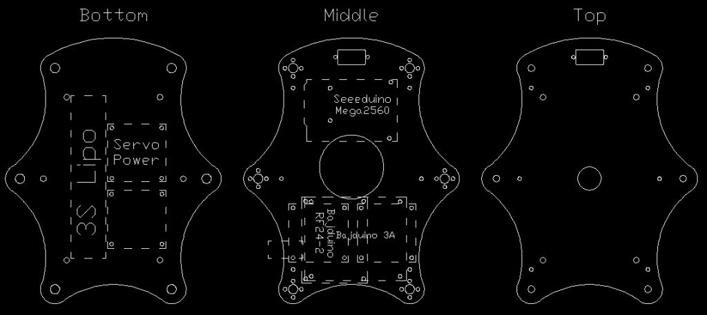
As you can see in the video I have removed the bottom plate of the chassis. I removed it so I could measure it. Then I started designing a new chassis in Autocad. This is the latest version:

Hexapod chassis

Hexapod chassis

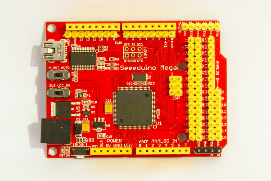
It consists of 3 plates, I’ll have them laser cut from acrylic. The design is far from finished. The bottom plate will hold the 3S Lipo, the power servo PCB and the UBECs. The middle plate will hold the electronics. I will use a Seeeduino Mega to control the servos and probably another micro controller for the rest. The design has mounting holes for all my Bajduino PCB’s. I haven’t decided which one I will fit.

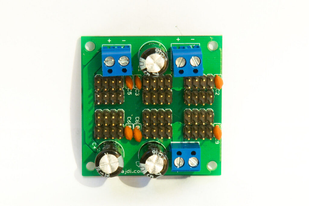
My first plan to power the hexapod was to use 2 UBECs. So I had designed a PCB where I could power 18 servos with 2 separate power supplies. Unfortunately the UBECs were not strong enough for my power hungry MG996R servos. So I had to resort to using 3 8A UBECs. I designed a new PCB so I could easily connect the 3 UBECs to the servos and micro controller. This is it:

RC Servo power board

RC Servo power board

The 3 8A UBECs are connected to the servo PCB. 18 wires with Dupont connectors connect the Seeeduino Mega with the servo power PCB. I chose the Seeeduino Mega as it is a lot smaller then the standard Arduino Mega. It’s about the same size as an Arduino Uno.

Seeeduino mega 2560

Seeeduino mega 2560

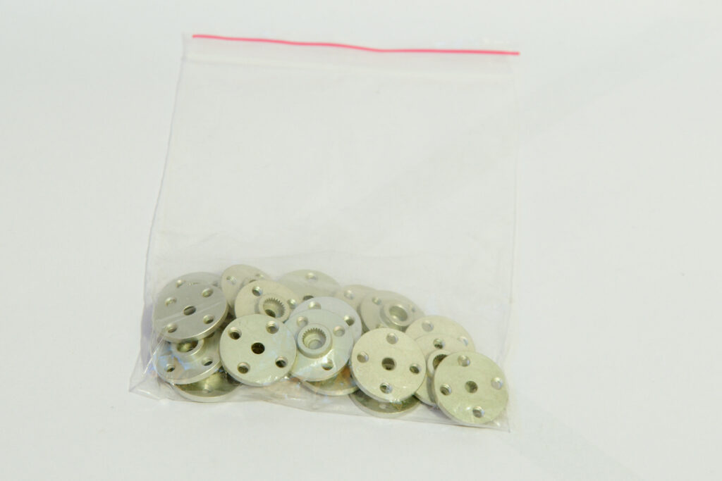
I have also received my metal servo horns. So I will fit these when I have the new chassis made.

Metal rc servo horns

Metal rc servo horns

Posted in Bajdupod 996R | Tagged hexapod, robot | 4 Responses

Bajdupod 996R: improved code :)

By Bajdi on March 23, 2013

Spent a lot of time working on the code of my Arduino hexapod this week. I reprogrammed the way I move the servos. The code is now based on a timer (millis) instead of using a for loop and the delay function. I can now control the speed of the walking gait. I also added a mode to move the body. There are still some glitches in the code that need further investigation. But I’m quite happy with the current result. The above video is running the last version of my code. The main hexapod sketch is now over 1000 lines code and takes up 35kb. The second micro controller on the hexapod that handles the wireless communication has 200 lines of code and is 10kb. The remote control is another 10kb sketch. So I’ve written lots of code the last weeks.

I should now spent some time on the mechanical side. The legs have very little grip at the moment so I need to find a solution to improve that. I’ve received 20 metal servo horns to replace the plastic ones. I’ll design a new chassis that is a little bigger then the current one. So I have enough room to mount the battery, UBECs and electronics inside the chassis. Currently the battery is zip tied to the bottom of the chassis. I’ll use 3 plates so I have 2 levels to mount all the electronics. The battery and servo power board in the lower deck and the micro controller in the upper deck. I’m expecting my new power servo PCB and Seeeduino Mega next week.

The hexapod consumes a lot of power. It will discharge a 3S 3000mAh Lipo battery in less then 10 minutes. I only have a small Lipo charger that charges @ 800mA. So it takes over 3 hours to charge the battery. So this morning I decided to order a fancy Imax B6AC charger. Of course I bought it on Ebay from a seller in Hongkong 🙂

Posted in Bajdupod 996R | Tagged hexapod, robot | 1 Response

« PreviousNext »

Recent Posts

  • 3D Printer extruders
  • Mearm forked
  • Arduino time lapse – camera pan device
  • Bought a 199$* Prusa I3 3D printer
  • Simple DIY lab power supply
  • Bajduino
    • Bajduino 1284
    • Bajduino 328
  • Stepper robot arm

Recent Comments

  1. 200+ Arduino Projects List For Final Year Students - He Loves Math on Obstacle avoiding robot made from cheap parts
  2. MP3 Alarm Clock: Crafting Customized wake-Up tunes with Arduino on Arduino MP3 alarm clock
  3. Bas on L9110 H-bridge module
  4. Victor on L9110 H-bridge module
  5. WAQAR AHMED on Dimming led with IR remote control

Archives

  • June 2016
  • August 2015
  • May 2015
  • January 2015
  • December 2014
  • November 2014
  • May 2014
  • April 2014
  • March 2014
  • February 2014
  • January 2014
  • December 2013
  • November 2013
  • October 2013
  • September 2013
  • June 2013
  • May 2013
  • April 2013
  • March 2013
  • February 2013
  • January 2013
  • December 2012
  • November 2012
  • October 2012
  • September 2012
  • August 2012
  • July 2012
  • June 2012
  • May 2012
  • April 2012
  • March 2012
  • February 2012
  • January 2012
  • December 2011

Categories

  • 3D printing
  • Arduino
  • Arduino sketches
  • Bajdupod 996R
  • Bajdupod 9G
  • Bob the biped
  • Buying parts
  • Dagu Rover 5
  • Dagu service droid
  • Gentoo
  • Insectbot
  • Line following robot
  • Raspberry Pi
  • Self balancing bot
  • Bajduino
    • Bajduino 1284
    • Bajduino 328
  • Stepper robot arm

Copyright © 2026 Bajdi electronics.

Powered by WordPress and Hybrid by Bajdi.