Dagu encoder kit
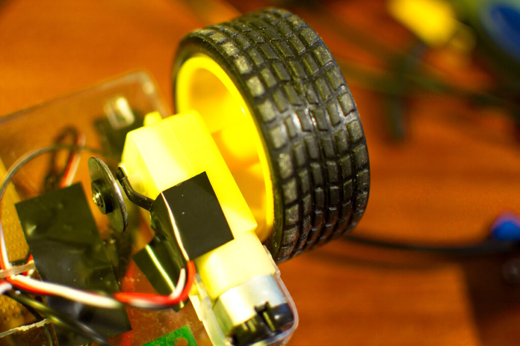
My little Ebay bot is powered by 2 cheap DC geared motors. These yellow geared DC motors are very popular. Lots of cheap robot kits use them. I bought mine on Ebay and used double sided tape to stick them to the chassis of the robot. I had one annoying problem with the cheapo motors. One was faster then the other. It took me some time to find the right PWM settings so they would run at approximately the same speed so the robot would drive in a straight line.
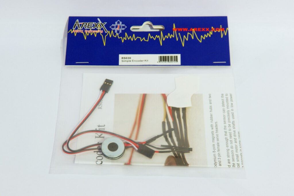
A better solution to this problem is to fit encoders to the motors. So I bought a Dagu simple encoder kit and fitted it to my Ebay bot. I attached the magnetic disc to the axle that drives the wheels. This is not ideal though. For better resolution you should try and mount the encoders to the motor axle. But the motor axle of my motors is unfortunately not long enough.
Motor encoder
There is a nice guide on how to use these encoders on Lets Make Robots. So I decided to try out the example code with my robot. And it didn’t really work… The example code was written for encoders that were fitted to the motor axle, these means you have a very high resolution. My encoders are fitted to the output axle of the gearbox so the encoders have a much lower resolution. The difference between a high and a low resolution is the number of pulses you get from the encoders. With my setup the encoders only give a pulse once every xx milliseconds when running fast and xxx milliseconds when running really slow. I did get the encoders to work after changing some of the code.
The code measures the time between 2 encoder pulses using interrupts. The speed of the motors is determined by a predefined time. This parameter is the time between 2 encoder pulses we want the motors to run. Shorter time means faster speed and longer time is slower. Because of the low resolution of my setup the example code would run so fast that the motors would just stop because so few pulses are measured. So I had to slow things down. I started by replacing the micros function with millis. Then I wrote some code that measures the time when the last pulse was detected. The code constantly adjusts the PWM of each motor. If the time since the last pulse is longer then what we want the PWM value is ramped up. If its shorter the PWM is lowered.
Here is my test sketch:
// http://www.bajdi.com
// Encoder test sketch
// Dagu simple encoder kit attached to yellow geared DC motors

// Motor controller pins:
const int EN1 = 3;        //enable motor 1 = pin 1 of L293D
const int direction1 = 13; //direction motor 1 = pin 2 of L293D
const int EN2 = 14;        //enable motor 2 = pin 9 of L293D
const int direction2 = 15; //direction motor 2 = pin 15 of L293D

// Motor speed
byte speedLeft = 160;        // start speed for left motor
byte speedRight = 160;      //  start speed for right motor

// Encoders
const int lEncoder = 10;    // interrupt 0
const int rEncoder = 11;    // interrupt 1
int motorTime = 120;                     // width of pulse in mS we want the motor to run (120 is pretty slow)
volatile unsigned long lpulse = 121;      // width of left encoder pulses in mS
volatile unsigned long rpulse = 121;      // width of right encoder pulses in mS
volatile unsigned long ltime;             // remembers time of left  encoders last state change in mS
volatile unsigned long rtime;             // remembers time of right encoders last state change in mS

#define runEvery(t) for (static typeof(t) _lasttime;(typeof(t))((typeof(t))millis() - _lasttime) > (t);_lasttime += (t))


void setup() {
  Serial.begin(9600); //to use the serial monitor
  pinMode(EN1, OUTPUT);
  pinMode(direction1, OUTPUT);
  pinMode(EN2, OUTPUT);
  pinMode(direction2, OUTPUT);
  analogWrite(EN1, 0);
  analogWrite(EN2, 0);
  digitalWrite(lEncoder,1);                               // enable pullup resistor for left  encoder sensor
  digitalWrite(rEncoder,1);                               // enable pullup resistor for right encoder sensor
  attachInterrupt(0,Lencoder,CHANGE);                     // trigger left  encoder ISR on state change
  attachInterrupt(1,Rencoder,CHANGE);                     // trigger right encoder ISR on state change
}

void loop() {

  runEvery(500)
  {
    Serial.print("lpulse = ");
    Serial.println(lpulse);
    Serial.print("rpulse = ");
    Serial.println(rpulse);
    Serial.print("speedLeft = ");
    Serial.println(speedLeft);
    Serial.print("speedRight = ");
    Serial.println(speedRight);
  }

  runEvery(5){                            // Run every 5ms, to fast would stop the motors
    int lastPulseL = millis() - ltime;     // Check how much time has passed since last pulse

   int lastPulseR = millis() - rtime;


    if (lastPulseL > motorTime && speedLeft < 255)    // If the pulse is longer then the time we want speed up motor
    {
      speedLeft = speedLeft+1;
    }
    if (lastPulseL < motorTime && speedLeft > 0)      // // If the pulse is shorter then the time we want slow down motor
    {
      speedLeft = speedLeft-1;
    }

    if (lastPulseR > motorTime && speedRight < 255)
    {
      speedRight = speedRight+1;
    }
    if (lastPulseR < motorTime && speedRight > 0)
    {
      speedRight = speedRight-1;
    }
  }
  forward();
  //backward();
  //left();
  //right();

}

void forward()
{
  digitalWrite(direction1, HIGH);
  digitalWrite(direction2, HIGH);
  analogWrite(EN1, speedLeft);
  analogWrite(EN2, speedRight);

}

void stop()
{
  digitalWrite(direction1, LOW);
  digitalWrite(direction2, LOW);
  analogWrite(EN1, 0);
  analogWrite(EN2, 0);

}

void backward()
{
  digitalWrite(direction1, LOW);
  digitalWrite(direction2, LOW);
  analogWrite(EN1, speedLeft);
  analogWrite(EN2, speedRight);

}

void left()
{
  digitalWrite(direction1, LOW);
  digitalWrite(direction2, HIGH);
  analogWrite(EN1, speedLeft);
  analogWrite(EN2, speedRight);

}

void right()
{
  digitalWrite(direction1, HIGH);
  digitalWrite(direction2, LOW);
  analogWrite(EN1, speedLeft);
  analogWrite(EN2, speedRight);

}


//======================================================= ISR for left encoder =======================================================
void Lencoder()
{
  lpulse=millis()-ltime;                               // time between last state change and this state change
  ltime=millis();  // update ltime with time of most recent state change
}

//======================================================= ISR for right encoder ======================================================
void Rencoder()
{
  rpulse=millis()-rtime;                               // time between last state change and this state change
  rtime=millis();  // update ltime with time of most recent state change
}
[…] started with the same code as I had written for my other robot and changed it for 4 motors. Next step is to integrate this […]
super useful – thanks for the tips.
Hi,
I am currently working with these cheap dc motors and need to obtain the position information of the robot. One of the method is to use quadrature encoder.
Do you have any suggestion on how can I do that? From what I see from your article, each sensor only able to provide one signal output. However, for quadrature encoder, it requires two signal output that are 90 degree out of phase.
Thanks in advance.
You don’t really need quadrature encoders, with one encoder signal and the direction you can calculate the distance travelled.
Just to be clear, does this code measure the distance traveled? Or is it only for measuring the rpm of the motor?
I have the same exact encoders and I attached them to the wheels of my robot. I am trying to measure the distance traveled.
If you know the rpm and the diameter of the wheels you can calculate the distance travelled…
Hello,
Is it possible to calculate the angle the motor had spin with this Encoder