Nrf24L01
I recently bought 4 Nrf24L01 modules, 2 small modules with internal antenna and 2 bigger ones with a preamp, amp and external antenna. You can find the small modules for less then 5$ a piece on Ebay. It’s the cheapest way make a wireless connection between 2 Arduino’s. These modules are based one the Nordic Semiconductor nRF24L01+ chip and use the SPI bus and 2 extra pins, you can find more information and how to connect them here. I found 2 libraries for these chips, the Mirf library on the Arduino playground and Maniacbugs RF24 library. I had some trouble getting these things to work, I searched the Arduino forum and it seems that I wasn’t the only one having issues with these modules and an Arduino Mega 2560. You can read about it here. After a lot of head scratching I got all 4 of the modules to work. I then tried to make some own sketches using the RF24 library and failed miserably. I have lot to learn when it comes to coding 🙁
I then tried out the Mirf library and had a bit more success. I managed to write 2 sketches (transmitter and receiver) that sent the analog value from one Arduino to the other. I think this is the minimum code you need to get them to work. Well it’s a start… I hope to use these modules to remote control a “robot”.
Here are the sketches:
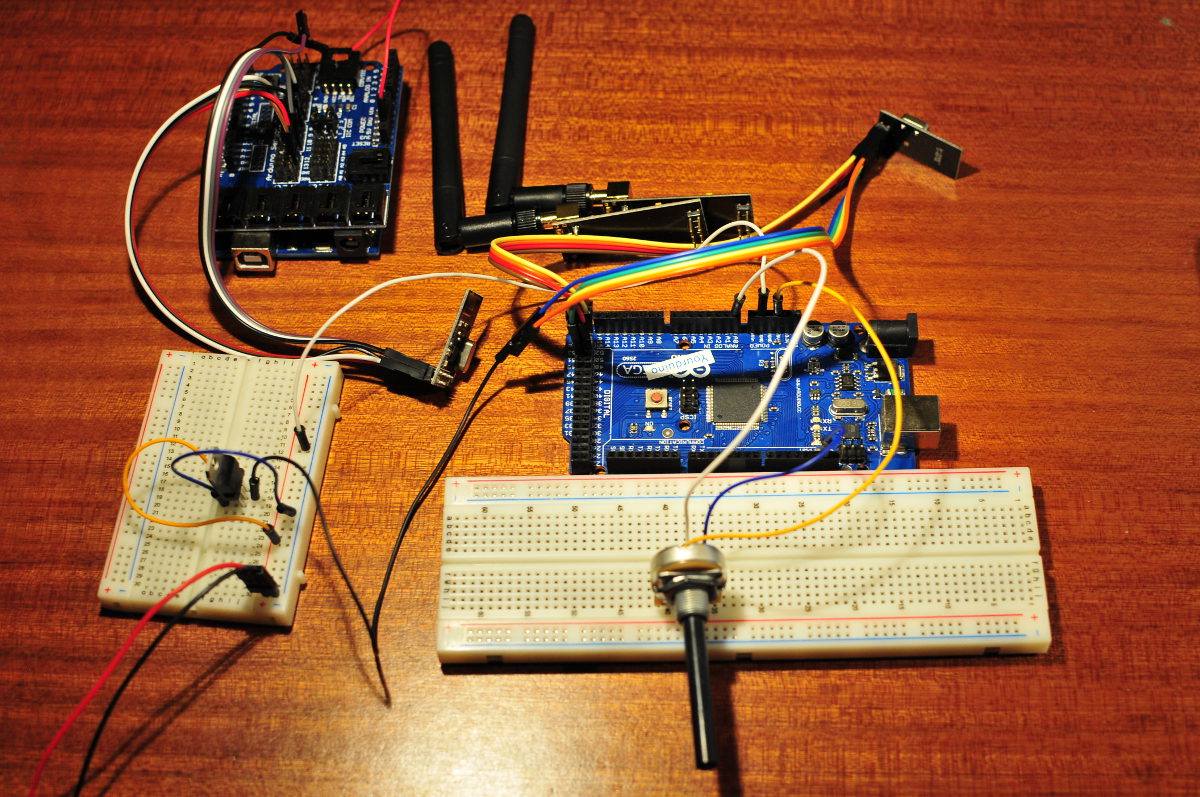
The following sketch goes in to the transmitter. (I used my Arduino Mega 2560 with a potentiometer connected to analog pin A0)
// http://www.bajdi.com
// Nrf24L01 connected to Mega 2560
// Nrf24L01 connection details http://arduino-info.wikispaces.com/Nrf24L01-2.4GHz-HowTo
// Transmit analog value from pin A0 to the receiver

#include <SPI.h>
#include <Mirf.h>
#include <nRF24L01.h>
#include <MirfHardwareSpiDriver.h>

int rate;

void setup(){

  Serial.begin(9600);
  Mirf.cePin = 48;             //ce pin on Mega 2560, REMOVE THIS LINE IF YOU ARE USING AN UNO
  Mirf.csnPin = 49;            //csn pin on Mega 2560, REMOVE THIS LINE IF YOU ARE USING AN UNO
  Mirf.spi = &MirfHardwareSpi;
  Mirf.init();
  Mirf.setRADDR((byte *)"clie1");
  Mirf.payload = sizeof(rate);
  Mirf.config();
}

void loop(){
  rate = analogRead(A0);

  Mirf.setTADDR((byte *)"serv1");

  Mirf.send((byte *) &rate);

  while(Mirf.isSending()){
  }
}
The following sketch goes in to the receiver Arduino. (from this Arduino we can read the analog value through the serial monitor)
// http://www.bajdi.com
// Nrf24L01 connected to Arduino Uno
// Nrf24L01 connection details http://arduino-info.wikispaces.com/Nrf24L01-2.4GHz-HowTo
// Receives analog value from transmitter and display it on serial monitor


#include <SPI.h>
#include <Mirf.h>
#include <nRF24L01.h>
#include <MirfHardwareSpiDriver.h>

int rate;

void setup(){

  Serial.begin(9600);

  Mirf.spi = &MirfHardwareSpi;
  Mirf.init();
  Mirf.setRADDR((byte *)"serv1");
  Mirf.payload = sizeof(rate);
  Mirf.config();
}

void loop(){

  while(!Mirf.dataReady()){
  }
  Mirf.getData((byte *) &rate);

  Serial.println(rate);
  delay(100);
}
With some small changes to the above sketch we can use the value read from the potentiometer (rate) and map it to a value between 0 and 255 to dim a led (analogwrite function).
// http://www.bajdi.com
// Nrf24L01 connected to Arduino Uno
// Nrf24L01 connection details http://arduino-info.wikispaces.com/Nrf24L01-2.4GHz-HowTo
// Receives analog value from transmitter and maps it to a PWM range (0-255) to dim a led


#include <SPI.h>
#include <Mirf.h>
#include <nRF24L01.h>
#include <MirfHardwareSpiDriver.h>

int rate;
int ledValue;

const int led = 3;

void setup(){

  Serial.begin(9600);
  pinMode(led, OUTPUT);
  Mirf.spi = &MirfHardwareSpi;
  Mirf.init();
  Mirf.setRADDR((byte *)"serv1");
  Mirf.payload = sizeof(rate);
  Mirf.config();
}

void loop(){

  while(!Mirf.dataReady()){
  }
  Mirf.getData((byte *) &rate);
  ledValue = (map( rate, 0, 1024, 0, 255 ) );
  analogWrite(led, ledValue);
  Serial.println(ledValue);
  delay(10);
}