By Bajdi on January 29, 2012
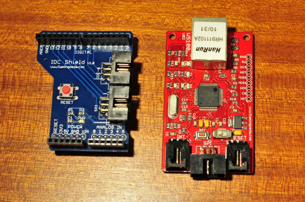
Flamingo EDA ethernet and IDC shield
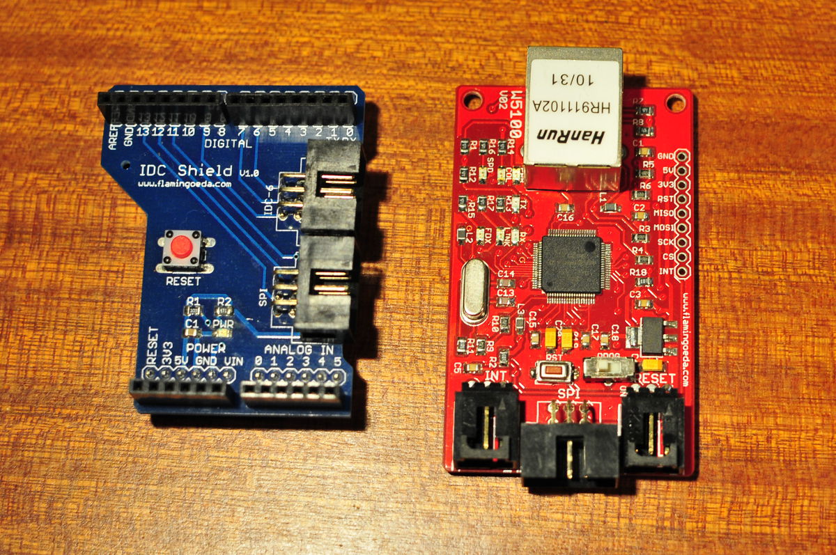
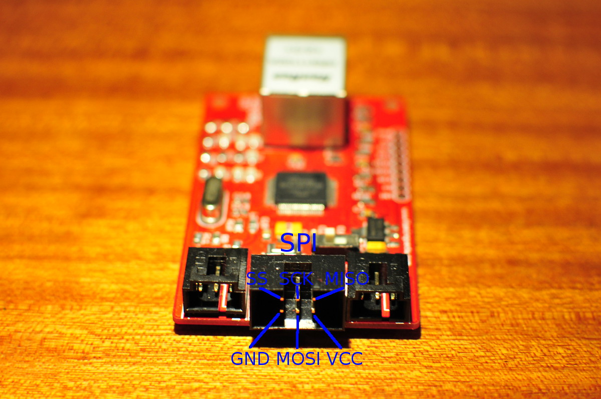
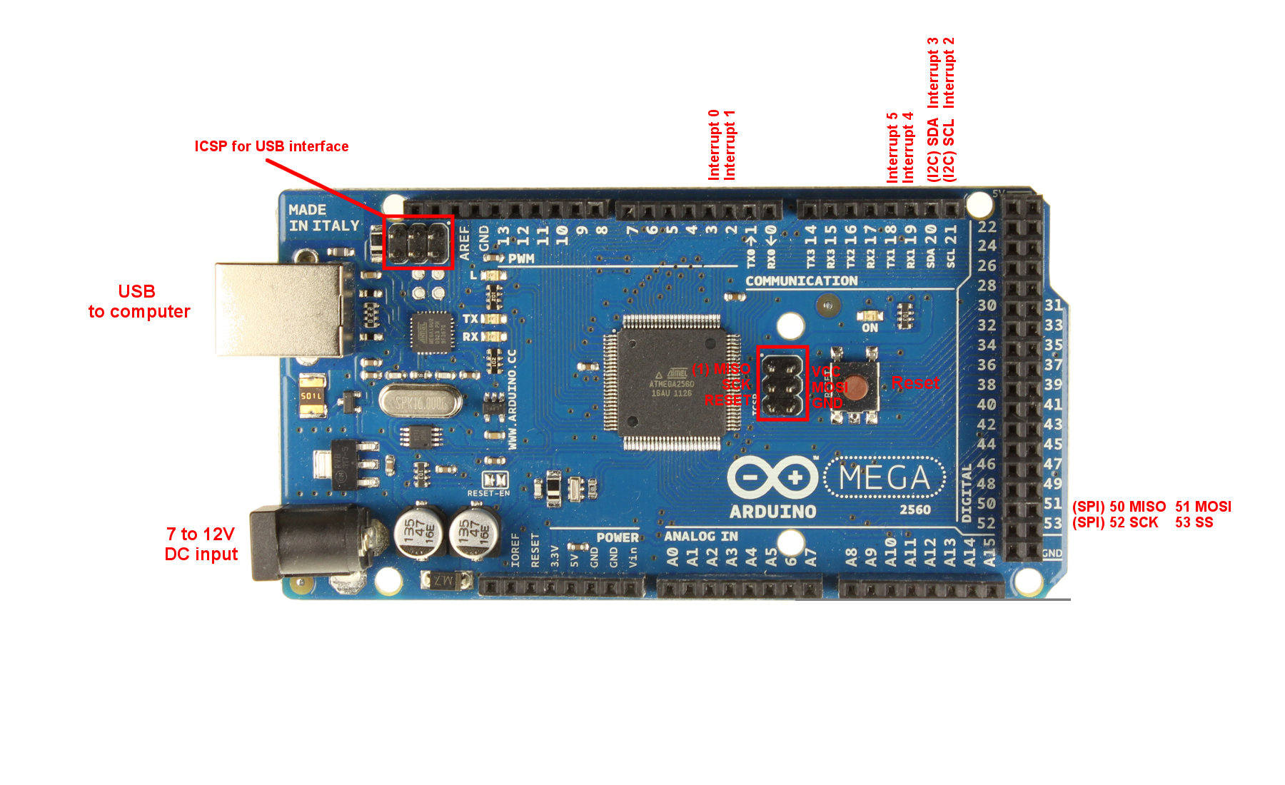
I’m working on a sketch that includes my Flamingo EDA ethernet module. The module I have is not a shield that you can plug on an Arduino but a separate board with the Wiznet W5100 chip on. I bought it together with the IDC shield, you can plug this shield on an Arduino Duemilanove/Uno and then connect both of the SPI connectors. I got it working on my Uno but this time I want to connect it to the Arduino Mega 2560. The IDC shield does not work on the Mega, because the Mega 2560 has a different location of the SPI pins. So I needed to find out which pin of the ethernet board is which pin of the SPI bus. The Flamingo EDA ethernet shield has 3 connectors, they are labelled INT, SPI and RESET. You only need to connect the SPI connector. I don’t know what the other 2 connectors are good for, maybe to update the firmware? I couldn’t find the pin layout online so I did some testing with my multimeter and found out how to connect it to my Mega. You can find the location of the SPI pins of the Arduino Mega 2560 on the official Arduino Mega 2560 page.
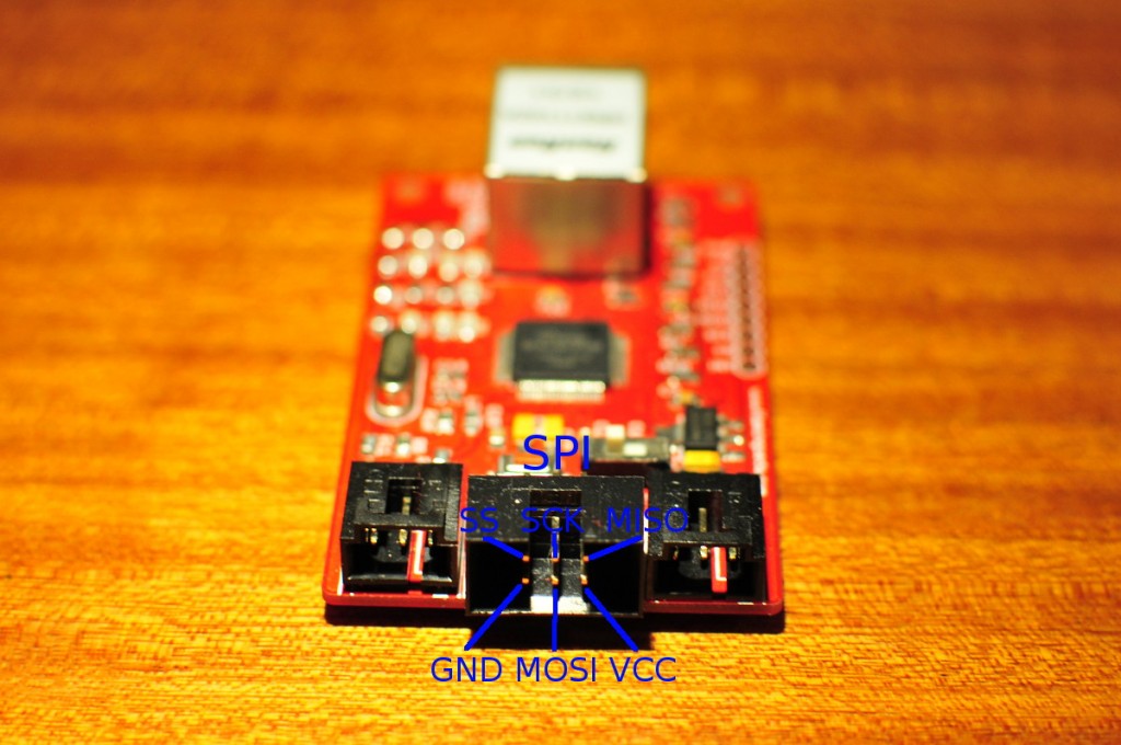
Flamingo EDA ethernet module
I edited the official photo of the Mega 2560 to include the SPI pin layout for easy reference.
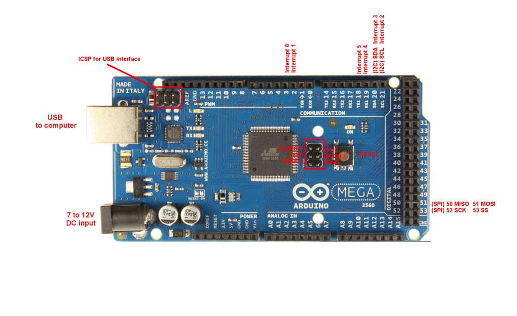
Arduino Mega 2560
Posted in Arduino |
By Bajdi on January 26, 2012
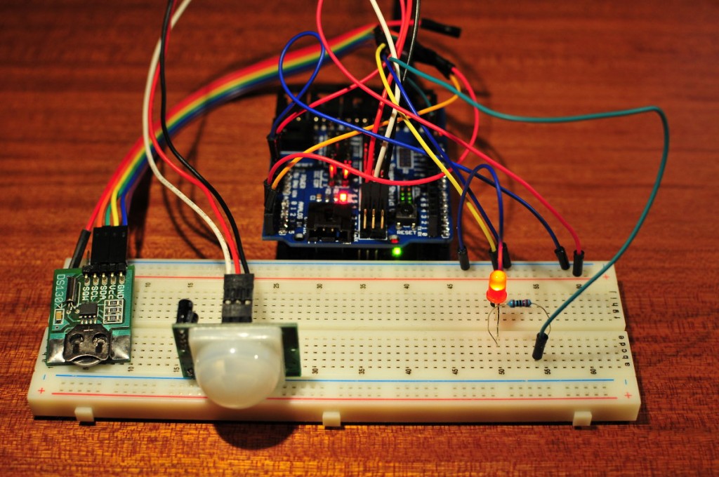
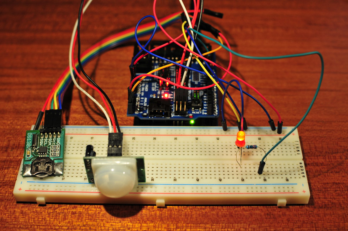
This time I have written a sketch to control a light with a PIR detector, well in this case the light is just a led. When the PIR detector detects movement it turns on the light, and after 30 seconds the light goes out. This is a common circuit in home automation, some of these PIR modules also have a clock so you can set the time for when it should work. There is no need to turn it on during the day when there is natural light. Since I have a DS1307 RTC module I thought why not try to make this myself.
I did not use the RTC library to get the time from the DS1307 but instead used code that I found here. With this code you can get the date and time from the DS1307, in the form of bytes over the I2C bus. The bytes are then converted to decimals so we can use them in our sketch. In this case we request the first 3 bytes, which are seconds, minutes and hours. In total you can request 7 bytes from the DS1307: second, minute, hour, day of the week, day of the month, month, year. I have made the sketch so that the PIR detector will turn on the the light after 18:00, and the light will turn off after 30 seconds.
The sketch:
/*
  http://www.bajdi.com
  PIR detector turns on light, light switches automatically off after 30 seconds.
  Light will only turn on in the evening (after 18:00)
 */

#include <Wire.h>
const int DS1307_I2C_ADDRESS = 0x68;
const int pir = 2;     // the number of the PIR pin
const int light =  13;      // the number of the light pin

unsigned long on;      //start time for pir light on

int pirState = 0;         // variable for reading the pushbutton status

byte second, minute, hour;

// Convert binary coded decimal to normal decimal numbers
byte bcdToDec(byte val)
{
  return ( (val/16*10) + (val%16) );
}


void getDateDs1307()
{
  // Reset the register pointer
  Wire.beginTransmission(DS1307_I2C_ADDRESS);
  Wire.send(0x00);
  Wire.endTransmission();

  Wire.requestFrom(DS1307_I2C_ADDRESS, 3);

  second     = bcdToDec(Wire.receive() & 0x7f);
  minute     = bcdToDec(Wire.receive());
  hour       = bcdToDec(Wire.receive() & 0x3f);  // Need to change this if 12 hour am/pm
}

void setup() {
  Wire.begin();
  pinMode(light, OUTPUT);
  pinMode(pir, INPUT);
}

void loop(){

  getDateDs1307();

  pirState = digitalRead(pir);

  if (pirState == HIGH && hour >= 18) {
    digitalWrite(light, HIGH);
    on = millis();
  }

  unsigned long currentMillis = millis();

  if ((currentMillis - on) > 30000) {
    digitalWrite(light, LOW);
  }

}
Posted in Arduino sketches |
By Bajdi on January 24, 2012
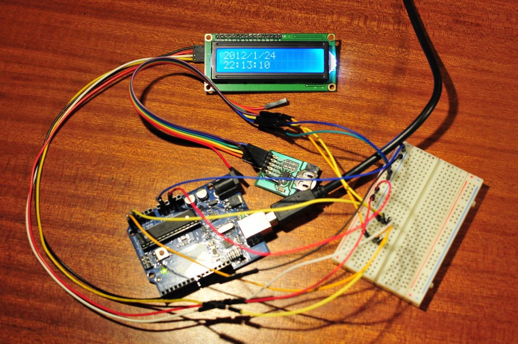
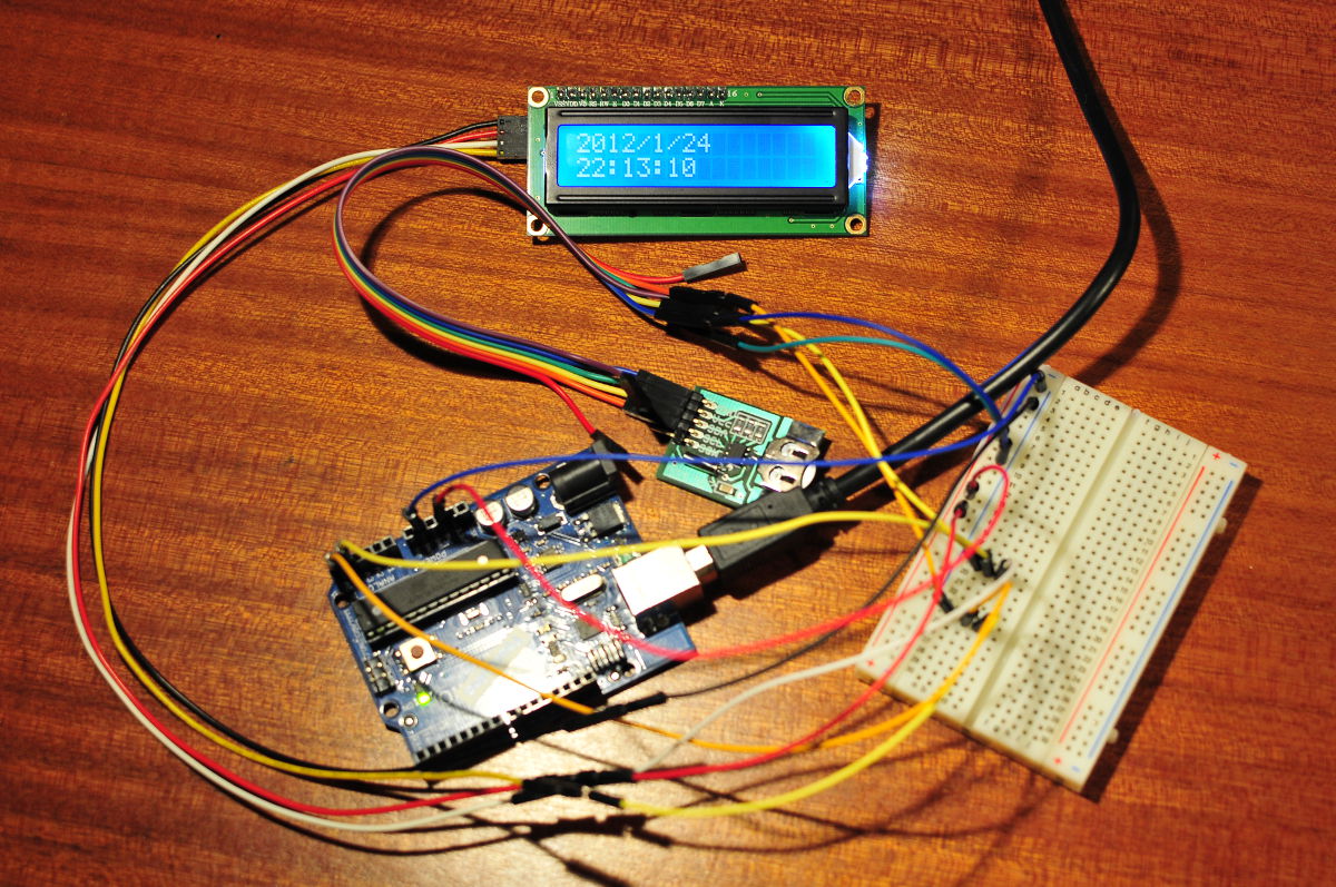
I found a DS1307 module in my mailbox today. The DS1307 is a serial real time clock, or RTC. You can easily find this chip at your favourite electronics dealer and make your own circuit with it. Several companies that make Arduino stuff sell modules with this chip. They all come with a small battery and an oscillator that is required to let the DS1307 do it’s thing. I found mine on Ebay from a Hungarian seller, arrived here pretty quickly so I immediately wanted to try it out.
Adafruit sells a board with the DS1307 chip and has made a nice library for it. It comes with an example that shows the time and date to the serial monitor. I changed the sketch to show the date and time on my I2C LCD display. The DS1307 is also an I2C device so I had to use my new little breadboard to connect both devices to the I2C pins of my Arduino Uno.
Here is the sketch:
// http://www.bajdi.com
// Arduino digital clock
// Date and time shown on I2C LCD display
// Date and time functions using a DS1307 RTC connected via I2C and Wire lib

#include <Wire.h>
#include "RTClib.h"
#include <LiquidCrystal_I2C.h>

LiquidCrystal_I2C lcd(0x27,16,2);

RTC_DS1307 RTC;

void setup () {
    Wire.begin();
    RTC.begin();
    lcd.init(); // initialize the lcd
    lcd.backlight();
  }

void loop () {
    DateTime now = RTC.now();
    lcd.clear();
    lcd.setCursor(0, 0);
    lcd.print(now.year(), DEC);
    lcd.print('/');
    lcd.print(now.month(), DEC);
    lcd.print('/');
    lcd.print(now.day(), DEC);
    lcd.setCursor(0, 1);
    lcd.print(now.hour(), DEC);
    lcd.print(':');
    lcd.print(now.minute(), DEC);
    lcd.print(':');
    lcd.print(now.second(), DEC);
    delay(1000);
}
An RTC module is a very handy device if you want to do some sort of data logging or other time based things. For example in a home automation program where you want to turn on devices at a certain time.
Posted in Arduino sketches |