By Bajdi on February 12, 2012
On friday DHL delivered my new toys 🙂 Arduino-direct have expanded their shop with robotics, and is now offering the Rover 5 and the Dagu controller boards. I had tried to order the Rover 5 at several European shops but none could deliver one, they were all out of stock. So I ordered it from Arduino-direct in China, and DHL flew it to Belgium. Took less then a week to get here.
The Rover 5 is a nice platform to make a tracked or wheeled robot. I bought the version with 4 motors and encoders. With the 4 motor version you can replace the tracks with normal wheels, I’ve seen a couple of videos of Rover 5’s with wheels from the Dagu Thumper fitted. The Rover 5 comes without any electronics fitted so you can choose how to control the motors. I went for the easy solution and bought the Dagu red back spider board and the 4 channel motor controller board. The red back spider is based on the Atmel ATMega 1280 and comes with the Arduino bootloader installed. The 4 channel motor controller has support for the 4 encoders.
The Rover 5 comes with a battery case for 6 AA batteries. But I’m thinking of replacing it with a Lipo battery. Easier to recharge then 6 AA’s. I will fit the Rover 5 with a nRF24L01 module so I can remote control it and 2 SRF06 ultrasonic sensors for collision detection. I’ll have to make some things myself, first thing will be a small print to supply the correct voltages to the different boards. I’ll need 3,3V for the nRF24L01 module and the accelerometer (if I decide to fit it) and 5V for the motor controller logic, but I could take that from the red back spider. Which has a powerful LM2676 5V 3A voltage regulator.
The reb back spider and motor controller board came with some stand-offs, but the Rover only has 4 holes to screw them in and they are to spaced to far from each other 🙁 So I’ve ordered some plexiglass and will use that to mount everything on. I’ve just wrote my first sketch to the red back spider to test the motors and got the motors to spin. I strongly recommend you take the tracks of when you first test it. I had to change the polarity of one connector to make all 4 of the motors spin in the same direction.
Posted in Dagu Rover 5 | Tagged robot |
By Bajdi on February 9, 2012
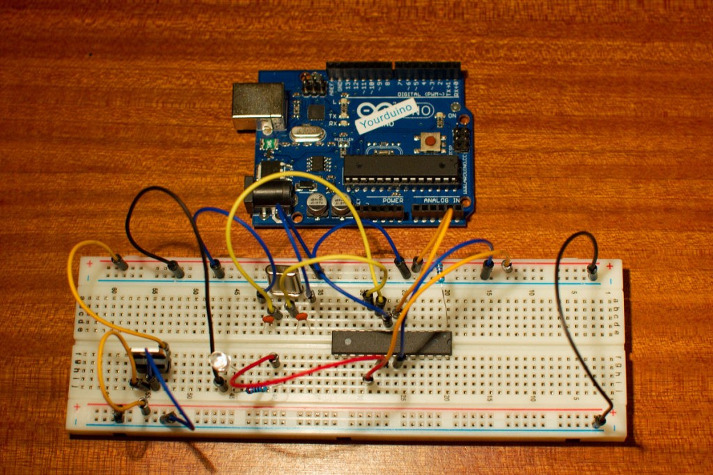
Arduino Uno on a breadboard
The Arduino Uno together with the Arduino IDE is an easy way to program the Atmel ATmega 328P micro controller. You don’t really need to buy an Arduino board if you want to play with the Arduino IDE. You can just buy an Atmel ATmega 328P, 2 capacitors, a crystal and a 10K resistor. Plug it on a breadboard and start playing. There is one issue though you need a way to put the sketch on the micro controller. The easiest method is to use an Arduino board if you already have one. Else you can buy an ISP programmer. The official Arduino website has instructions on how to accomplish this.
I bought an Atmel ATmega 328P from the official Arduino store, it already had the Arduino Uno boot loader preprogrammed. Making it all a lot easier. I used these instructions to connect the 328P to my Uno. It did need to search for some things before I could connect it all. The website doesn’t have the pinout of the ATmega 328P, you can download the data-sheet from the Atmel website. The Arduino pin numbers are not the same as the ones Atmel uses in their data-sheet but I found that information here.
To connect it all you only need 2 ceramic capacitors, a crystal and a 10K resistor. I had bought a set of ceramic capacitors from Arduino-direct some time ago. I didn’t know that the little numbers on them were not the value but capacitors codes. I found the information on how these translate to the value of the capacitor on this website.
After uploading the sketch I powered the ATmega 328P on the breadboard from my lab power supply through a L7805CV voltage regulator and it worked 🙂 It’s all pretty straightforward, no special tricks are involved. So now I know it’s not that difficult to make my own Arduino board 🙂
Posted in Arduino | Tagged ATmega328P-PU |
By Bajdi on February 6, 2012
Arduino: wireless contol of 2 stepper motors from Bajdi on Vimeo.
A month ago I wrote a sketch to control 2 little stepper motors with an analog joystick. After getting the Nrf24L01 modules to work last week I wanted to connect the joystick to one Arduino and the stepper motors to another Arduino. It was easier then I thought, I just put the 2 analog values from the joystick in an array. Then we can sent that array to the other Arduino and that’s about it 🙂 I connected the little 28YBJ-48 stepper motors to my Arduino Mega 2560 and the joystick to my Uno. As you can see in the video I’m using 2 different Nrf24L01 modules, the one connected to the Mega 2560 has a preamp and amp the one connected to the Uno is the small version with integrated antenna. I have 2 of each of these modules, but I seemed to have blown one up. I mistakenly connected 5V to one of the small modules and it’s dead 🙁 Already ordered a couple of new ones on Ebay 🙂 Luckily it was only a small module, I paid 20$ a piece for the big modules with preamp and amp, I’m NOT going to blow those up.
Here is the code I used:
Transmitter code:
<pre>// http://www.bajdi.com
// Nrf24L01 connected to Arduino Uno
// Nrf24L01 connection details http://arduino-info.wikispaces.com/Nrf24L01-2.4GHz-HowTo
// Transmit analog values from joystick to the receiver

#include <SPI.h>
#include <Mirf.h>
#include <nRF24L01.h>
#include <MirfHardwareSpiDriver.h>

int joystick[2];

void setup(){

  Serial.begin(9600);
  Mirf.spi = &MirfHardwareSpi;
  Mirf.init();
  Mirf.setRADDR((byte *)"clie1");
  Mirf.payload = sizeof(joystick);
  Mirf.config();
}

void loop(){
  joystick[0] = analogRead(A0);
  joystick[1] = analogRead(A1);
  Serial.println(joystick[0]);
  Serial.println(joystick[1]);

  Mirf.setTADDR((byte *)"serv1");

  Mirf.send((byte *) &joystick);

  while(Mirf.isSending()){
  }
}
Receiver code:
// http://www.bajdi.com
// Nrf24L01 connected to Arduino Mega 2560
// Nrf24L01 connection details http://arduino-info.wikispaces.com/Nrf24L01-2.4GHz-HowTo
// Receives analog values (joystick) from transmitter and moves stepper motors left/right forward/backward

#include <SPI.h>
#include <Mirf.h>
#include <nRF24L01.h>
#include <MirfHardwareSpiDriver.h>
#include <Stepper.h>

const int stepsPerRevolution = 64;

Stepper small_stepper(stepsPerRevolution, 8,10,9,11);
Stepper small_stepper2(stepsPerRevolution, 4,6,5,7);

int joystick[2];

void setup(){

  small_stepper.setSpeed(250);    // set first stepper speed
  small_stepper2.setSpeed(250);   // set second stepper speed
  Mirf.cePin = 48;             //ce pin on Mega 2560
  Mirf.csnPin = 49;            //csn pin on Mega 2560
  Mirf.spi = &MirfHardwareSpi;
  Mirf.init();
  Mirf.setRADDR((byte *)"serv1");
  Mirf.payload = sizeof(joystick);
  Mirf.config();
}

void loop(){

  while(!Mirf.dataReady()){
  }
  Mirf.getData((byte *) &joystick);

  if (joystick[0] < 490) {
    small_stepper.step(1);
  }   // step forward
  if (joystick[0] > 540) {
    small_stepper.step(-1);
  }  // step backward

  if (joystick[1] < 490) {
    small_stepper2.step(1);
  } // step left
  if (joystick[1] > 540) {
    small_stepper2.step(-1);
  } // step right
}
Posted in Arduino sketches | Tagged 28BYJ-48, nRF24L01 |
