Bajdi electronics

Hobby electronics website

Browse: Page 4

Using touch screen as remote control

By Bajdi on April 5, 2014

Arduino due and tft

Arduino due and tft

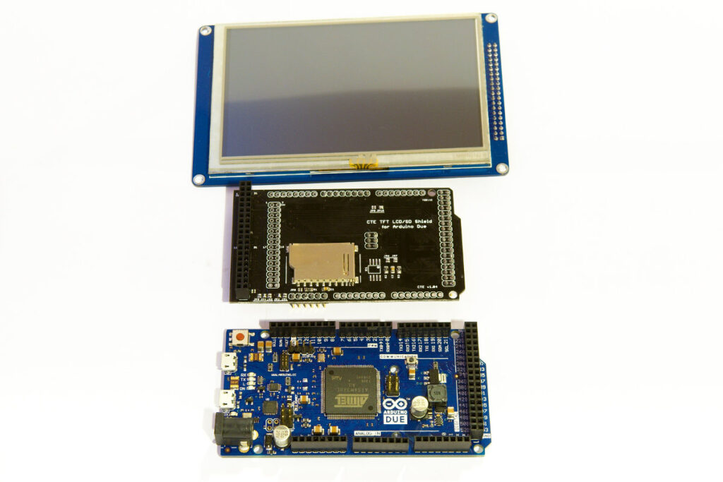
I’ve been playing with a 5″ TFT touch screen. I bought the TFT a while ago and quickly came to the conclusion that an adaptor shield is the best solution to connect it to an Arduino. These touch screen TFT’s use a lot of pins. Another issue is that the controller chip for the TFT works at 3.3V. So you need to level shift all those pins if you want to connect it to a 5V Arduino. I bought an adaptor shield for the Arduino Mega. I then started writing some simple code for it and came to another conclusion. You need a fast micro controller if you want to show some fancy things on your TFT. So I spent some more money and bought an Arduino Due (32bit ARM @ 84MHz). The adaptor shield for the mega doesn’t work with the Due so I also bought a new adaptor shield for the Due on Ebay.

You need 2 libraries to make the TFT and touch function work. I’m using the UTFT and UTouch libraries, I found them here. These libraries are not the most simple, but luckily they come with a manual that explains the libraries functions. When you first use the TFT touch screen you must calibrate it. The UTouch library comes with a sketch to calibrate your display.

One of the things I wanted to try out was using the touch screen as a remote control. I have a lot of cheap nRF24L01 modules so I soldered one to the adaptor shield. Thankfully someone has ported the RF24 library to make it work with the Arduino Due. I made a simple sketch to remotely control 4 leds with the touch screen using the wireless nRF24L01 modules:

Here is the code for the Arduino Due with the touch screen and nRF24L01 module:

// Arduino Due + 5" TFT touch screen + nRF24L01 = bling bling remote control
// http://www.bajdi.com

#include <UTFT.h>
#include <UTouch.h>
#include <UTFT_Buttons.h>
#include <SPI.h>
#include "nRF24L01.h"
#include "RF24.h"

RF24 radio(8, 9);
const uint64_t pipe = 0xE8E8F0F0E1LL;

uint8_t remote;

extern uint8_t SmallFont[];
extern uint8_t BigFont[];
extern uint8_t Dingbats1_XL[];

UTFT myGLCD(CTE50, 25, 26, 27, 28);
UTouch        myTouch(6, 5, 4, 3, 2);
UTFT_Buttons  myButtons(&myGLCD, &myTouch);

int pressed_button;
const int X = 90;
const int Y = 50;
int led1OnBut, led2OnBut, led3OnBut, led4OnBut, led1OffBut, led2OffBut, led3OffBut, led4OffBut;

void setup()
{
  Serial.begin(57600);
  radio.begin();
  radio.setPALevel( RF24_PA_MAX ) ;
  radio.setDataRate(RF24_1MBPS);
  radio.openWritingPipe(pipe);

  myGLCD.InitLCD();
  myGLCD.clrScr();
  myGLCD.fillScr(VGA_WHITE);
  myGLCD.setFont(BigFont);

  myTouch.InitTouch();
  myTouch.setPrecision(PREC_HI);

  myButtons.setTextFont(BigFont);

  led1OnBut = myButtons.addButton(X, Y, 150,  80, "Led 1 On");
  led2OnBut = myButtons.addButton(X + 155, Y, 150,  80, "Led 2 On");
  led3OnBut = myButtons.addButton(X + 310, Y, 150,  80, "Led 3 On");
  led4OnBut = myButtons.addButton(X + 465, Y,  150,  80, "Led 4 On");

  led1OffBut = myButtons.addButton(X, Y + 100, 150,  80, "Led 1 Off");
  led2OffBut = myButtons.addButton(X + 155, Y + 100, 150,  80, "Led 2 Off");
  led3OffBut = myButtons.addButton(X + 310, Y + 100, 150,  80, "Led 3 Off");
  led4OffBut = myButtons.addButton(X + 465, Y + 100,  150,  80, "Led 4 Off");
  myButtons.drawButtons();
}

void loop()
{
  if (myTouch.dataAvailable() == true)
  {
    pressed_button = myButtons.checkButtons();

    if (pressed_button == led1OnBut)
    {
      remote = 1;
    }
    else if (pressed_button == led2OnBut)
    {
      remote = 2;
    }
    else if (pressed_button == led3OnBut)
    {
      remote = 3;
    }
    else if (pressed_button == led4OnBut)
    {
      remote = 4;
    }
    else if (pressed_button == led1OffBut)
    {
      remote = 5;
    }
    else if (pressed_button == led2OffBut)
    {
      remote = 6;
    }
    else if (pressed_button == led3OffBut)
    {
      remote = 7;
    }
    else if (pressed_button == led4OffBut)
    {
      remote = 8;
    }
  }
  radio.write( &remote, sizeof(remote) );
}

And the code for the receiver:

#include <SPI.h>
#include "nRF24L01.h"
#include "RF24.h"

uint8_t remote;

const int led1 = 18;
const int led2 = 17;
const int led3 = 16;
const int led4 = 15;

// nRF24L01 radio
RF24 radio(1,2);
const uint64_t pipe = 0xE8E8F0F0E1LL;

void setup(){
  Serial.begin(57600);
  pinMode(led1, OUTPUT);
  pinMode(led2, OUTPUT);
  pinMode(led3, OUTPUT);
  pinMode(led1, OUTPUT);

  radio.begin();
  radio.setPALevel( RF24_PA_MAX ); 
  radio.setDataRate(RF24_1MBPS);
  radio.openReadingPipe(1,pipe);
  radio.startListening();
}

void loop(){

  if ( radio.available() )
  {
    // Dump the payloads until we've gotten everything
    bool done = false;
    while (!done)
    {
      // Fetch the payload, and see if this was the last one.
      done = radio.read( &remote, sizeof(remote) );
    }
  }
  switch (remote){
  case 1:
    digitalWrite(led1, HIGH);
    break;

  case 2:
    digitalWrite(led2, HIGH);
    break;

  case 3:
    digitalWrite(led3, HIGH);
    break;

  case 4:
    digitalWrite(led4, HIGH);
    break;

  case 5:
    digitalWrite(led1, LOW);
    break;

  case 6:
    digitalWrite(led2, LOW);
    break;

  case 7:
    digitalWrite(led3, LOW);
    break;

  case 8:
    digitalWrite(led4, LOW);
    break;
  }
  // Serial stuff
  Serial.print("remote = ");
  Serial.println(remote);
  // end of serial stuff
}
Posted in Arduino | Tagged nRF24L01, TFT | 4 Responses

Controlling an Arduino through a Rapsberry Pi webserver

By Bajdi on March 19, 2014

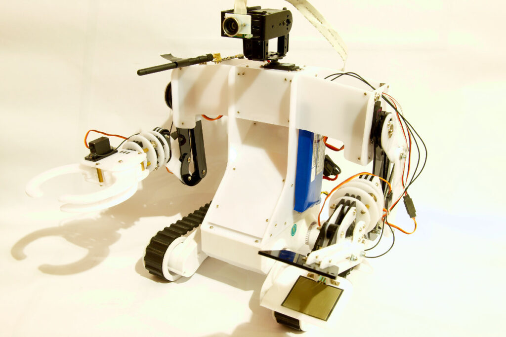
I’ve been looking for ways to control my Service droid robot, my Service droid robot has an ATmega2560 (with Arduino bootloader) and a Raspberry Pi. My goal is to control it over wifi. But I wanted to start with some more simpler things first. I’ve recently found some python code on letsmakerobots.com that lets me sent data over I2C from a Raspberry Pi to a micro controller.

Before getting this to work you need to configure I2C on the Raspberry Pi. Adafruit has written a nice guide how to do this. I also installed the python-SMBus package: sudo apt-get install python-smbus.

The Raspberry Pi’s gpio pins are 3.3V and my ATmega runs at 5V so I used a logic level converter to connect both. I connected my Bajduino Mega 3A board to the Raspberry Pi. My big Bajduino has an I2C logic level converter on board so I didn’t need to connect any extra electronics.
To test the Raspberry Pi I2C to Arduino connection I found some useful information on Oscar Liangs blog.

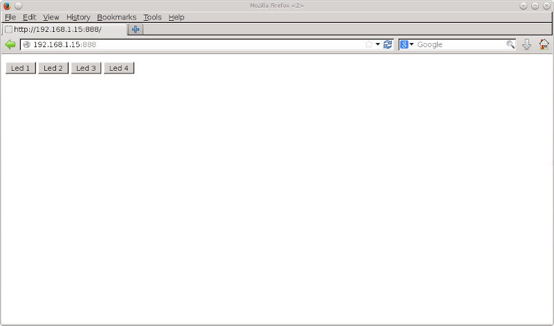
I then started modifying the code I found on letsmakerobots so the small webserver serves a webpage with 4 buttons. By pressing a button the python code will sent a command over I2C to the ATmega. By pressing the buttons I can control 4 leds connected to the ATmega. The webserver runs on port 888, I tried running it on the default webserver port 80 but couldn’t get it to work. I also have to run it as root, else I couldn’t access the I2C pins. This is a security issue, not something you want to try running on the internet.

The webpage:

You can download the python code here: webserver.txt (rename to .py)
Here is the Arduino sketch

I’m not sure if I will use this code to control my service droid robot. I’ve also been looking at using Apache with cgi to run python code. This is a bit harder to setup and write code for. So I’m still a long way of to control my robot over wifi with my Raspberry Pi 🙁

Posted in Raspberry Pi | Tagged I2C, python, webserver | 4 Responses

Fitted wide angle lens to raspberry pi camera

By Bajdi on February 16, 2014

Dagu service droid

Dagu service droid

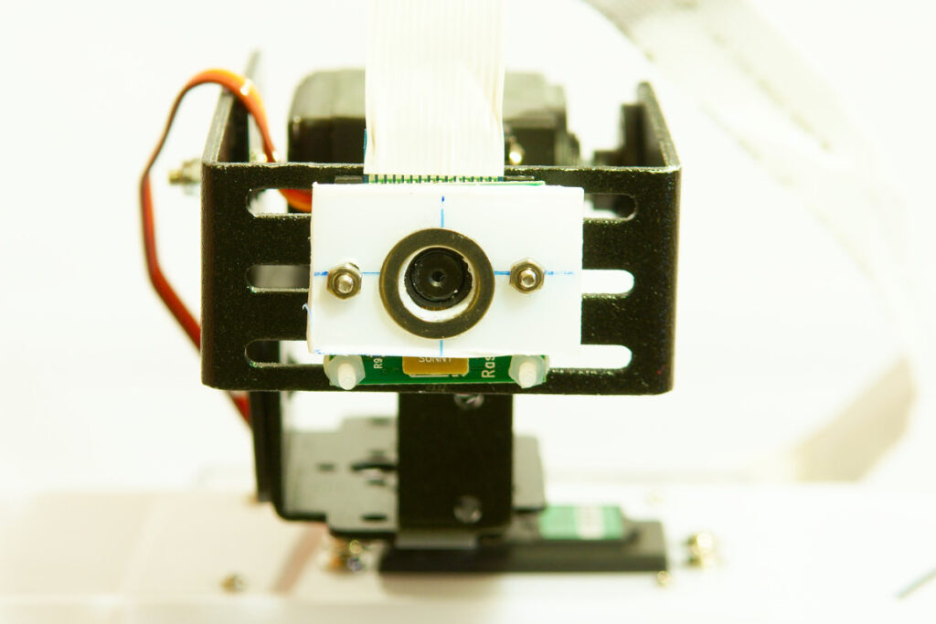
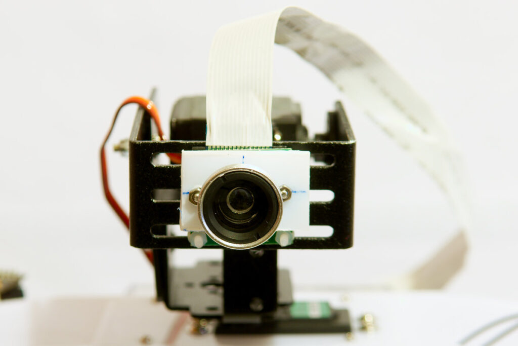
Bought me a set of mini Iphone lenses on Ebay, cost less then 10€. Since the viewing angle of the Raspberry Pi camera is pretty narrow I decided to try out a wide angle lens. My camera board is fitted to a pan/tilt kit on my Service droid robot. The narrow viewing angle makes it hard to accurately remote control the robot. I couldn’t resist the Iphone lenses when I saw how cheap they are. To fit them to an Iphone you have to stick a metal ring around the camera. The lens has a magnetic edge to make it stick to the ring. I was a bit worried if I would succeed in attaching it to the Raspberry Pi camera board but in the end it was quite easy.

I used a small piece of polystyrene plate and cut it to approximately the size of the Raspberry Pi camera board. I then drilled 3 holes in it. Two 2mm holes in the edge of the plate and 1 big 8mm hole in the middle. I used M2 nuts and bolts to fit the plate to the camera board. I then stuck the ring to the plate and fitted it to the camera board.

Then I could fit the mini lens to the ring 🙂

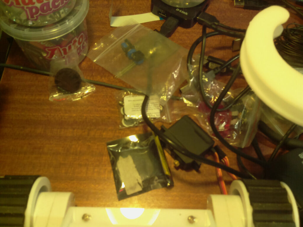
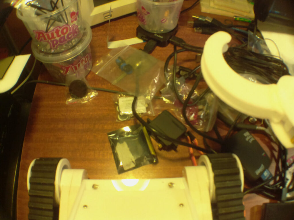
The difference is not that big and the photos and videos made with the lens are not as sharp. But still it was worth the trouble. Here are 2 photos made with the camera board without and with the lens fitted:

Without the lens fitted:

With the lens fitted:

Posted in Raspberry Pi | Tagged Raspberry Pi | Leave a response

« PreviousNext »

Recent Posts

  • 3D Printer extruders
  • Mearm forked
  • Arduino time lapse – camera pan device
  • Bought a 199$* Prusa I3 3D printer
  • Simple DIY lab power supply
  • Bajduino
    • Bajduino 1284
    • Bajduino 328
  • Stepper robot arm

Recent Comments

  1. 200+ Arduino Projects List For Final Year Students - He Loves Math on Obstacle avoiding robot made from cheap parts
  2. MP3 Alarm Clock: Crafting Customized wake-Up tunes with Arduino on Arduino MP3 alarm clock
  3. Bas on L9110 H-bridge module
  4. Victor on L9110 H-bridge module
  5. WAQAR AHMED on Dimming led with IR remote control

Archives

  • June 2016
  • August 2015
  • May 2015
  • January 2015
  • December 2014
  • November 2014
  • May 2014
  • April 2014
  • March 2014
  • February 2014
  • January 2014
  • December 2013
  • November 2013
  • October 2013
  • September 2013
  • June 2013
  • May 2013
  • April 2013
  • March 2013
  • February 2013
  • January 2013
  • December 2012
  • November 2012
  • October 2012
  • September 2012
  • August 2012
  • July 2012
  • June 2012
  • May 2012
  • April 2012
  • March 2012
  • February 2012
  • January 2012
  • December 2011

Categories

  • 3D printing
  • Arduino
  • Arduino sketches
  • Bajdupod 996R
  • Bajdupod 9G
  • Bob the biped
  • Buying parts
  • Dagu Rover 5
  • Dagu service droid
  • Gentoo
  • Insectbot
  • Line following robot
  • Raspberry Pi
  • Self balancing bot
  • Bajduino
    • Bajduino 1284
    • Bajduino 328
  • Stepper robot arm

Copyright © 2026 Bajdi electronics.

Powered by WordPress and Hybrid by Bajdi.