By Bajdi on January 16, 2012
ADXL345
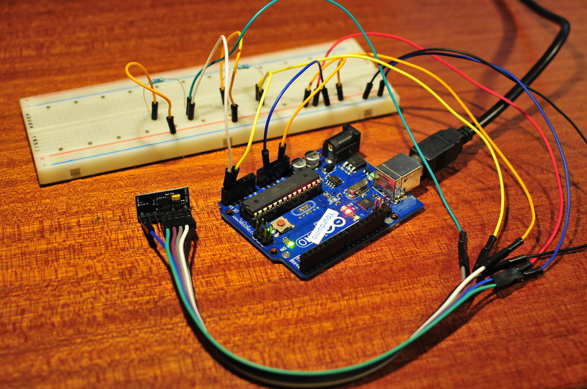
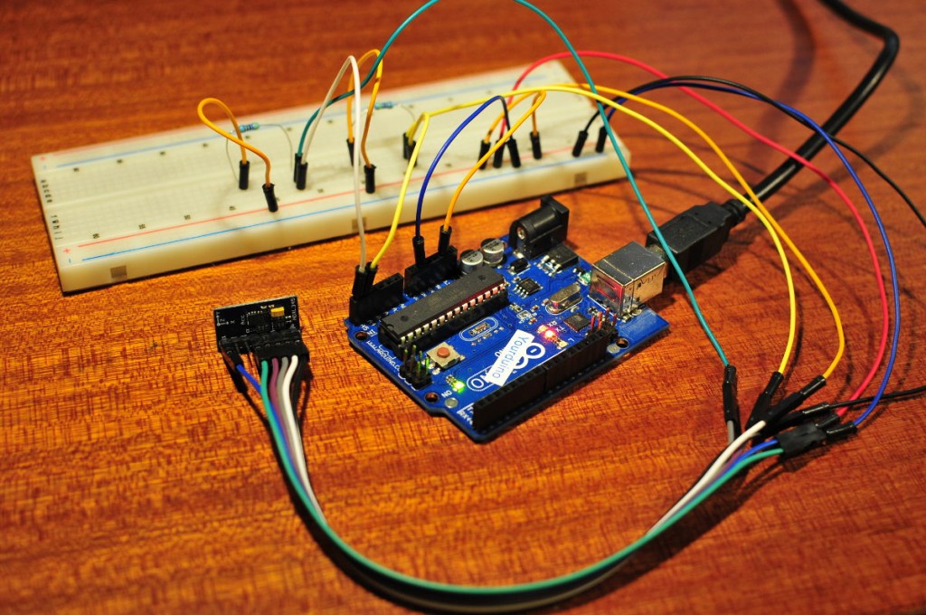
The mail man delivered some pin headers (2€ for 5 x 40 pins on Ebay) last week and I found some time to solder them to my ADXL345 board. So it was time to start playing with the ADXL345 accelerometer. I had a look around the various tutorials on the internet and found lots of different diagrams for connecting it to an Arduino. So I consulted the data sheet, and read that the ADXL345 can be used on the SPI or the I2C bus. I will be using it on the I2C bus as the Arduino library for the ADXL345 is written for I2C and it’s the easiest way to connect it. My ADXL345 breakout board has 8 pins: GND, VDD, SCL, SDA, SDO, INT2, INT1 and CS. The ADXL is not 5V tolerant so do not connect the VDD pin with the 5V but with the 3,3V pin on your Arduino. To use the I2C bus the datasheet states that pin CS should be high, so connect that also to 3,3V. Since the I2C bus on the Arduino is 5V we need to use pullup resistors to 3,3V. I used 2 4k7 resistors between SDA and SCL and 3,3V. Something else I found in the datasheet is that you can select the I2C address by pulling the SDO pin high or low. So you can choose between 2 addresses. This is handy if you have other devices on the I2C bus. The library has 2 examples, I compiled both and let them run. After some fiddling I managed to get the ADXLRun345 example sketch running. I could see the x, y and z values change on the serial monitor while moving the board around, it works 🙂 I needed to add “Accel.powerOn();” in void setup, I assume my ADXL345 doesn’t “start” automatically when it receives power. After taking a good look at these example sketches I’ve come to realise that I still have a lot to learn. I don’t understand much of them. The ADXL345 is a pretty advanced sensor with lots of features. I think it’s going to take a long time before I can do something useful with it.
/**************************************************************************
 *                                                                         *
 * ADXL345 Driver for Arduino                                              *
 *                                                                         *
 ***************************************************************************
 *                                                                         *
 * This program is free software; you can redistribute it and/or modify    *
 * it under the terms of the MIT License.                                  *
 * This program is distributed in the hope that it will be useful,         *
 * but WITHOUT ANY WARRANTY; without even the implied warranty of          *
 * MERCHANTABILITY or FITNESS FOR A PARTICULAR PURPOSE.  See the           *
 * MIT License for more details.                                           *
 *                                                                         *
 ***************************************************************************
 *
 * Revision History
 *
 * Date  By What
 * 20100515 TJS Initial Creation
 * 20100524 TJS Modified to run with Kevin Stevenard's driver
 */
#include "Wire.h"
#include "ADXL345.h"

ADXL345 Accel;

void setup(){
  Serial.begin(57600);
  delay(1);
  Wire.begin();
  delay(1);
  Serial.println("Here");
  Accel.powerOn();
  Accel.set_bw(ADXL345_BW_12);
  Serial.print("BW_OK? ");
  Serial.println(Accel.status, DEC);
  delay(1000);
}

void loop(){
  int i;
  double acc_data[3];
  Accel.get_Gxyz(acc_data);
  if(Accel.status){
    float length = 0.;
    for(i = 0; i < 3; i++){
      length += (float)acc_data[i] * (float)acc_data[i];
      Serial.print(acc_data[i]);
      Serial.print(" ");
    }
    length = sqrt(length);
    Serial.print(length);
    Serial.println("");
    delay(40);
  }
  else{
    Serial.println("ERROR: ADXL345 data read error");
  }
}
Some interesting links I found while searching for info on the ADXL345:
Posted in Arduino sketches | Tagged ADXL345 |
By Bajdi on January 13, 2012
Find the number game
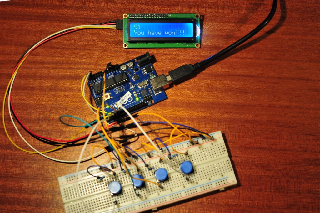
I think I have programmed my first computer game. Computer being an 8bit micro controller 🙂 I hooked up 4 push buttons and an I2C LCD to an Arduino Uno. The first push button adds 1 to the number shown on the LCD, the second detracts 1, the third multiplies the number by 2 and the fourth divides by 2. The goal is to find a random number between 0 and 99. This was my first struggle, how do you generate a random number in Arduino? The C/C++ language has the random function but this generates the same value every time you setup the Arduino. So someone smarter then me made a library that generates true random numbers based on the noise of the analog 0 input. There is one downside, this library doesn’t work with the Arduino Mega. Strange but that’s the way it is. By using the “abs” function the sketch will calculate the difference of the number and the random number, based on this difference the LCD will tell if you are close to the random number. It did take me some time before I came up with a sketch that did what I wanted, but I learned some new things. And that was the reason I made this 🙂
Here is the sketch:
// http://www.bajdi.com
// Find a number between 0 and 99 with 4 push buttons.
// The first push adds 1, second button subtracts 1,
// the third button multiplies by 2, the fourth button divides by 2
// Numbers are displayed on an I2C LCD.
// Use the reset button on the Arduino to restart the game.
// The TrueRandom library does NOT work with the Arduino Mega

#include <Wire.h>
#include <LiquidCrystal_I2C.h>
#include <TrueRandom.h>

LiquidCrystal_I2C lcd(0x27,16,2);

const int buttonplus = 2;    // the number of the +1 pushbutton pin
const int buttonmin = 3;    // the number of the -1 pushbutton pin
const int button2 = 4;    // the number of the x2 pushbutton pin
const int buttond2 = 5;    // the number of the /2 pushbutton pin
const int led =  13;
int buttonpluspresses = 0;
int buttonminpresses = 0;
int tempnumber;

int lastButtonplusState;
int lastButtonminState;
int lastButton2State;
int lastButtond2State;
int ledState = LOW;

int readingplus = 0;
int readingmin = 0;
int reading2 = 0;
int readingd2 = 0;

const int winningnumber = TrueRandom.random(100);

void setup() {
  pinMode(buttonplus, INPUT);
  pinMode(buttonmin, INPUT);
  pinMode(button2, INPUT);
  pinMode(buttond2, INPUT);
  pinMode(led, OUTPUT);

  lcd.init(); // initialize the lcd
  lcd.backlight();
}

void loop()
{

  readingplus = digitalRead(buttonplus);
  readingmin = digitalRead(buttonmin);
  reading2 = digitalRead(button2);
  readingd2 = digitalRead(buttond2);

  if (tempnumber <= 0)
  {
  tempnumber = 0;
  }

  lcd.setCursor(0, 0);
  lcd.print(tempnumber);

  if (readingplus != lastButtonplusState)
  {
    if (readingplus == LOW)
    {
    buttonpluspresses ++;
    tempnumber = tempnumber + buttonpluspresses;
    lcd.setCursor(0, 0);
    lcd.print(tempnumber);
    }
    lastButtonplusState = readingplus;
    buttonpluspresses = 0;
    }
  if (readingmin != lastButtonminState)
  {
    if (readingmin == LOW)
    {
    buttonminpresses ++;
    tempnumber = tempnumber - buttonminpresses;
    lcd.setCursor(0, 0);
    lcd.print(tempnumber);
    }
    lastButtonminState = readingmin;
    buttonminpresses = 0;
  }
  if (reading2 != lastButton2State)
  {
    if (reading2 == LOW)
    {
    tempnumber = tempnumber * 2;
    lcd.setCursor(0, 0);
    lcd.print(tempnumber);
    }
    lastButton2State = reading2;
  }
  if (readingd2 != lastButtond2State)
  {
    if (readingd2 == LOW)
    {
    tempnumber = tempnumber / 2;
    lcd.setCursor(0, 0);
    lcd.print(tempnumber);
    }
    lastButtond2State = readingd2;
  }

  if (tempnumber == winningnumber)
  { lcd.setCursor(0,1);
    lcd.print("You have won!!!!");
    digitalWrite(led, HIGH);
  }
  if (tempnumber != winningnumber)
  {
    digitalWrite(led,LOW);
  }
  if (abs(tempnumber - winningnumber) > 10)
   {
    lcd.setCursor(0,1);
    lcd.print("Try harder");
   }
  if (abs(tempnumber - winningnumber) <= 10 && abs(tempnumber - winningnumber) > 3)
   {
    lcd.setCursor(0,1);
    lcd.print("Close");
   }
  if (abs(tempnumber - winningnumber) <= 3 && abs(tempnumber - winningnumber) >= 1)
   {
    lcd.setCursor(0,1);
    lcd.print("Very close");
   }
  delay(150);
  lcd.clear();
 }
Posted in Arduino sketches |
By Bajdi on January 13, 2012

SRF06 ultrasonic range finder
I’ve played with an SRF06 range finder this week. The SRF06 is an ultrasonic distance measuring module. They are ideal to sense objects, so I bought 2 to put on the front and back of a robot. The Arduino library for these modules gives you the detected distance in centimeters or inches.
You can find the library and a basic sketch that sends the distance to the serial monitor here. These kind of sensors are used in cars to help drivers when parking.
So I started by making a basic sketch that would detect an object and would light a bunch of leds as the object comes closer just like the parking help I have in my car.
/*
  http://www.bajdi.com
  SRF06 module detecting distance in cm. The closer we get to the object
  the more leds start to burn.
  The circuit:
 * leds on pin 2,3,4,5
 * SRF06 module: trig to pin 12, echo to pin 13
*/

#include "Ultrasonic.h"

const int  TRIG = 9;
const int  ECHO = 10;
const int led1 = 2;
const int led2 = 3;
const int led3 = 4;
const int led4 = 5;
Ultrasonic SRF06(TRIG, ECHO);

void setup()
{
  pinMode(led1, OUTPUT);
  pinMode(led2, OUTPUT);
  pinMode(led3, OUTPUT);
  pinMode(led4, OUTPUT);
}

void loop()
{
  if (SRF06.Ranging(CM) >= 100)
  {
    digitalWrite(led1, LOW);
    digitalWrite(led2, LOW);
    digitalWrite(led3, LOW);
    digitalWrite(led4, LOW);
  }
  if (SRF06.Ranging(CM) >= 80 && SRF06.Ranging(CM) < 100)   {     digitalWrite(led1, HIGH);     digitalWrite(led2, LOW);     digitalWrite(led3, LOW);     digitalWrite(led4, LOW);   }   if (SRF06.Ranging(CM) >= 60 && SRF06.Ranging(CM) < 80)   {     digitalWrite(led1, HIGH);     digitalWrite(led2, HIGH);     digitalWrite(led3, LOW);     digitalWrite(led4, LOW);   }   if (SRF06.Ranging(CM) >= 40 && SRF06.Ranging(CM) < 60)
  {
    digitalWrite(led1, HIGH);
    digitalWrite(led2, HIGH);
    digitalWrite(led3, HIGH);
    digitalWrite(led4, LOW);
  }
  if (SRF06.Ranging(CM) < 40)
  {
    digitalWrite(led1, HIGH);
    digitalWrite(led2, HIGH);
    digitalWrite(led3, HIGH);
    digitalWrite(led4, HIGH);
  }
}
I’ve looked around on the internet to find the datasheet for the SRF06 but haven’t been able to find it. The SRF06 is an improved version of the SRF04, I wonder if they have the same specifications. Some info that I’ve found of the SRF06:
- power supply :5V
- DC quiescent current : less then 2mA
- effective angle: less then 15°
- ranging distance : 2cm – 500 cm
- resolution : 0.3 cm
Posted in Arduino sketches | Tagged ultrasonic |