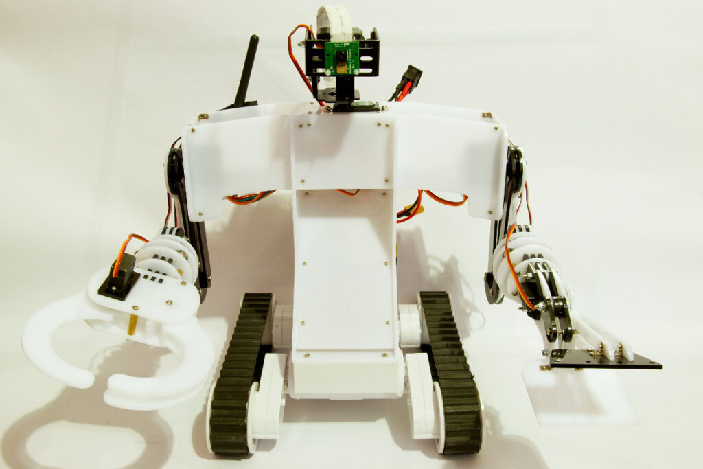
Dagu service droid
Decided it was time to add a Raspberry Pi to my Dagu service droid. I already had a Pi shell so that came in handy to attach the Raspberry Pi to the service droid. It has 2 mounting holes in the back which are ideal to mount it. I drilled 2 holes in the back of the torso of the service droid, had to take the torso apart to be able to do this. I then used 2 brass spacers to bolt it in place.
Dagu service droid with raspberry pi
I then fitted the Raspberry Pi camera board to the pan/tilt kit using nylon screws and spacers. The cable that comes with the Camera board was not long enough so I bought a longer (25cm) cable on Ebay. I immediately tried the camera and came to conclusion that the viewing angle is pretty narrow. I also couldn’t move the camera down enough to be able to see the gripper and pincer. So I decided to modify the pan/tilt kit so it sits higher above the torso. I used some metal brackets I had laying around and bolted them together. Now the camera can look down so I can see the gripper and pincer and also the front edge of the robot. Which is handy to accurately position the robot. I have ordered a wide angle lens for a smartphone on Ebay. That should give me a wider viewing angle, if I manage to fit it to the camera board…
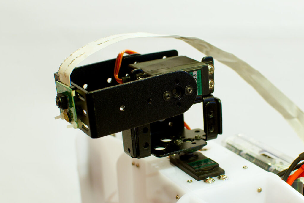
Dagu service droid with pan tilt kit
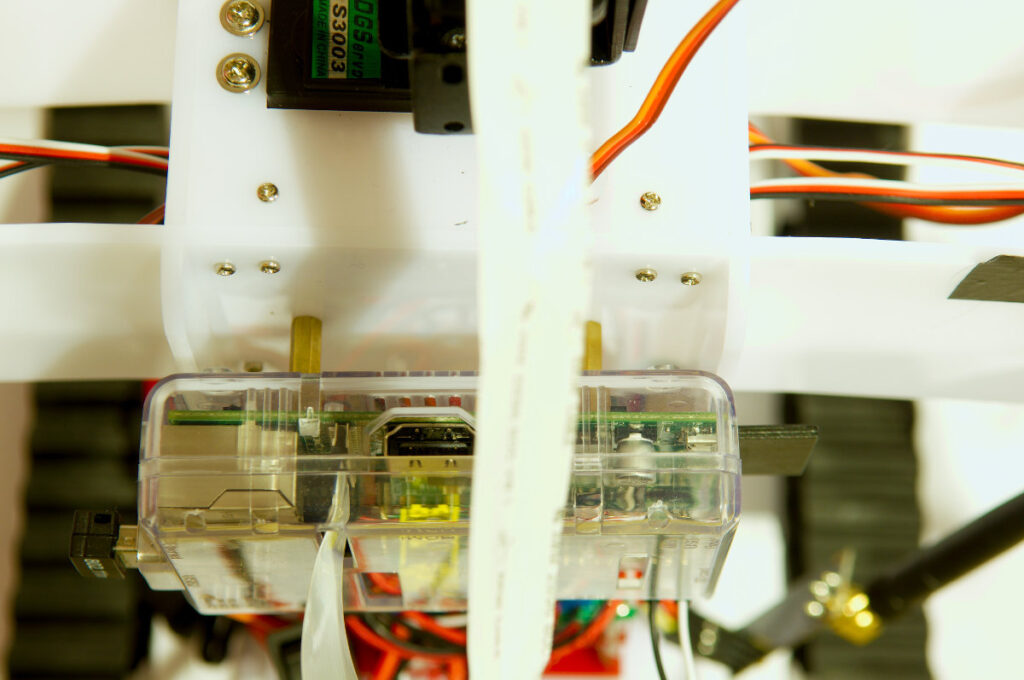
To power the Raspberry Pi I run 2 wires from the RPi to the Dagu red back spider controller. It has a 3A 5V switch mode regulator so can give more then enough current. At the moment it only powers the RPi.
This is the back of my Dagu service droid showing the different parts:
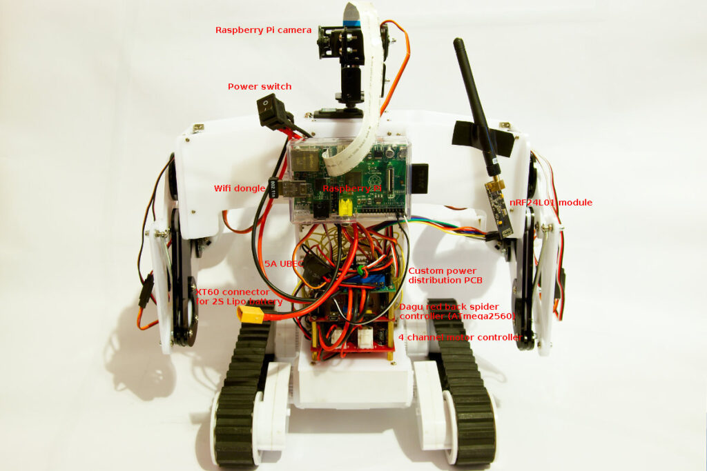
Dagu service droid back view
I made a cable with a power switch and a 10A automotive blade fuse to power the robot. The cable has an XT60 connector to connect the battery. I made the cable pretty long as I haven’t decided yet where I’m going to put the battery. The biggest 2S Lipo battery I currently have is a 3000mAh one, I’ll probably order a bigger one from Hobbyking in the near future. I used flexible AWG16 silicon insulated wire to make the cable.
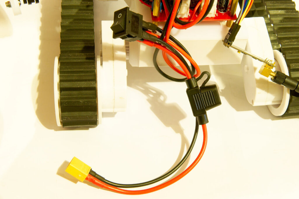
Dagu service droid power cable
To wire up my first Rover 5 I had used premade cables to connect the motor controller and sensors to the micro controller. This time I made my own wires with Dupont connectors. I’ve bought some new tools to attach Dupont connectors to wires.
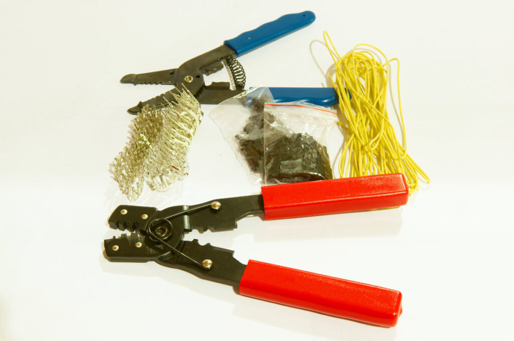
Tools for making Dupont connectors
By making my own wires I can minimize the wire mess. The Rover 5 chassis I’m using has 4 motors with encoders. I’ve also attached the current feedback pins of the motor controller. In total I use 16 pins on the micro controller to control the motors. 4 digital outputs for the direction, 4 pwm pins to control the speed, 4 interrupt pins for the encoders and 4 analog inputs for the current feedback. I also use one analog input to monitor the battery voltage. I’m using an ATmega2560 micro controller which has a lot of I/O.
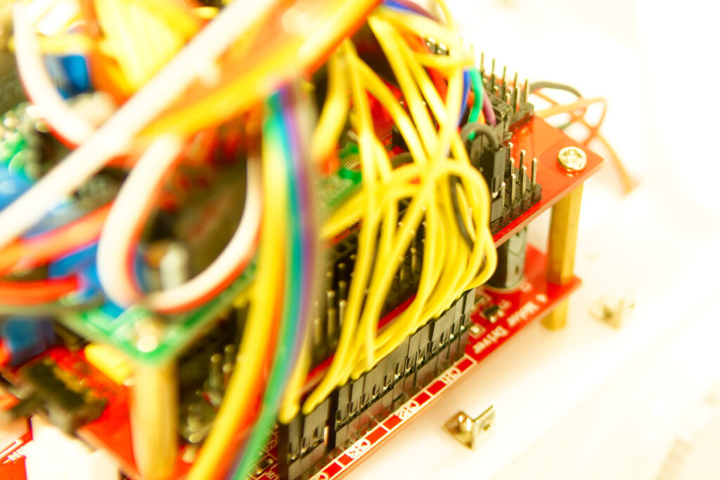
Dagu service droid wiring
I’ve found a fantastic Pi camera web interface on the Raspberry Pi forums. Installed it and then let the service droid drive around. I’m still using my Arduino remote control with 2 nRF24L01 modules. This didn’t work very well. Both the nRF24L01 and the Wifi dongle work @ 2.4GHz, they don’t seem to mix very well. The nRF24L01 modules were dropping a lot of packets.
My plan is to remove the nRF24L01 module and control the robot over Wifi. I want to make a web interface using node.js. I don’t have any experience with node.js so it will take me some time to figure out. The idea is that the Raspberry Pi runs a webpage with buttons to control the robot. When pressing the buttons on the webpage the RPi sends commands over serial to the micro controller. The output of the camera should be shown on the same webpage.
I’m also adding some sensors to the robot. Have not decided how much and which sensors I will add. At the moment I’m experimenting with an ACS712 current sensor to detect if a servo is stalled. I might add 2 of these sensors, one for the gripper and one for the pincer.