Arduino nano undershield
Almost a year ago I designed my first PCB. It was a small 50x50mm PCB that acts as an undershield for an Arduino Nano. I designed it because the Arduino Nano has a tiny 5V voltage regulator. To not overheat the regulator you can not draw more then 200-300mA from it depending on the input voltage. Since I use Lipo batteries for most of my projects I also needed a regulator to power a couple of small servos. So I thought why not design a shield with a cheap 3A 5V switch mode regulator (LM2576). 3A is more then enough for a couple of servos and some sensors. The added benefit is that the switch mode regulator is much more efficient then a linear regulator. Which is a good thing when you use battery power.
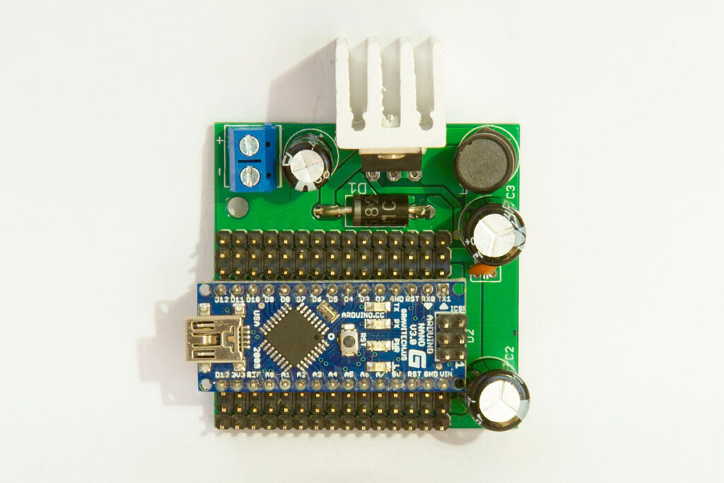
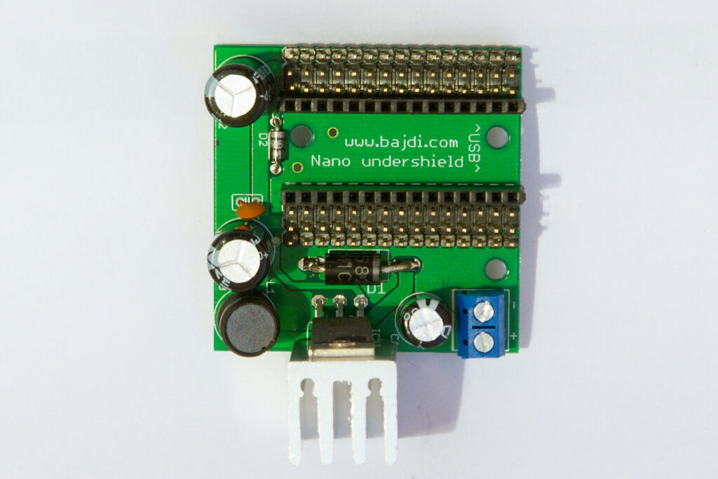
While my first design worked it had a couple of small mistakes. Some of the holes were not big enough and some of the traces were a bit on the thin side. So I decided to make an improved version. In this version the Nano gets its power through the Vin pin. It is connected to the screw terminal through a schottky diode. Next to the Nano there are 3 rows of pins. The row with pins closest to the Nano are connected to the pins on the Nano. The middle row is the 5V, which comes from the 3A regulator. The outer row of pins are the ground pins. These 3 rows of pins make it very easy to connect servos and sensors to the Arduino Nano without have to worry if they get power enough. I’ve done some testing with the board and even connected 10 little servos to it. The regulator could handle the servos but the 5V line becomes very noisy. It does not effect the Nano though since it doesn’t get power from the regulator. With a small heatsink like the one in the photo below the regulator is good for about 2A without overheating.
Arduino nano undershield
Parts used:
1x PCB made by Seeedstudio
1x Screw terminal with 2 positions 5mm (Tayda Electronics)
1x Capacitor 100µF 50V (Tayda Electronics)
1x LM2576 5V (Tayda Electronics)
1x TO220 heatsink (Tayda Electronics)
1x 100µH 3A inductor (Ebay)
2x Capacitor 1000µF 25V (Ebay)
1x 1N5822 3A diode (Tayda Electronics)
1x 100nF 50V Ceramic capacitor (Tayda Electronics)
1x 1N5818 Schottky diode (Tayda Electronics)
A couple of strips of male and female headers (Tayda Electronics)
I had 10 of these PCB’s made by Seeedstudio, I wont be needing them all. If you would like to have one sent me an email: info|@|bajdi d|0|t com
Hello, this project looks really interesting, I’m currently tinkering on a project fairly similar to drive motors and pixel mapped LED tape using a nano, but with fewer outputs – I don’t suppose you’d have a circuit schematic, or ideally a pcb design handy at all? – I would make sure to credit you in all documentation produced 🙂
Thanks,
James
Design your own PCB’s, it’s not that hard. You can download the Eagle files of my pro mini undershield here: http://www.bajdi.com/arduino-pro-mini-undershield/