VS1053 MP3 module
There are several MP3 shields available for Arduino. Most of them are based on the VLSI VS1053 chip. I’m not a fan of the shield system as it limits you which pin on the shield connects to the micro controller. Also my own “Bajduinos” are not shield compatible.
Thankfully there are some break out boards available with the VS1053 chip. I bought one on Ebay for less then 8€. It’s made by LCsoft. I did a bit of googling before I bought the board and found some sketches and Arduino libraries for the VS1053 chip. So I thought it would be easy to make an Arduino play MP3’s. Of course it turned out to be a bit different…
No matter which sketch or library I tried I could not get the damn thing to work. I thought that I maybe had a faulty board until I found Maniacbugs VS1053 midi library. I installed the library and tried the example sketch. The example sketch makes the chip play a simple midi file. And for the first time I got some music out of the VS1053 module 🙂 Unfortunately this library only supports midi files. I wanted to let my Arduino play MP3’s…
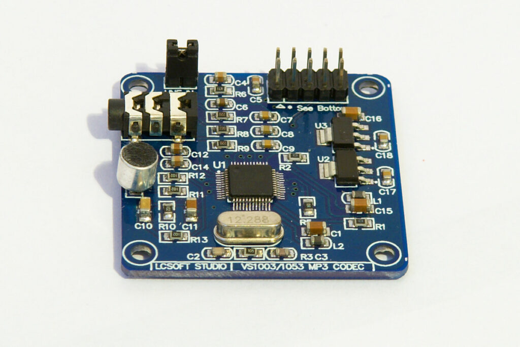
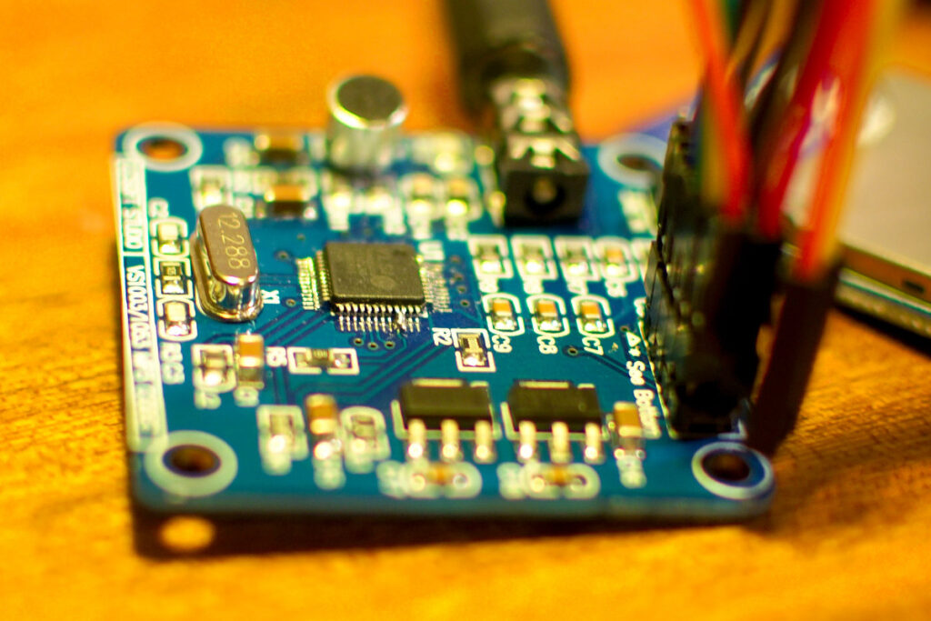
I was about to give up on it until someone pointed me to this topic on the VLSI support forums. Looks like the LCsoft board is missing a trace or resistor to make it play mp3’s. The board boots the VS1053 chip in midi mode. Thankfully it’s possible to modify it and boot it in mp3 mode. You just need to solder a bridge connecting pin 33 and 34. I used my thinnest (0.2mm) solder tip to solder the bridge. Here is a photo of the modification I made:
LCsoft VS1053 MP3 module
I then tried out the example sketch of this library. And it worked, finally I had an Arduino that could play mp3’s 🙂
Some handy links:
VS1053 specification and datasheet: http://www.vlsi.fi/en/products/vs1053.html
Arduino library for the VS1053 chip: http://mpflaga.github.io/Sparkfun-MP3-Player-Shield-Arduino-Library/
Support forum for the above library: http://www.billporter.info/forum/forum/sparkfun-mp3-shield-support-forum/
[…] I used an LCsoft VS1053 MP3 module and a small 0,25W speaker (bought from Tayda Electronics) to play MP3′s. The VS1053 MP3 module is also connected to the SPI pins of the Arduino. The LCsoft module needs to be modified to make it play MP3′s. You can read about that in my previous post. […]
Hello,
Thanks so much !!! Had same problem and soldering those pins saved me ! So many days wasted to try all combinations…
Have fun with all your projects.
Bye
Hi ,
thanks for all your tips !
I have a question to you :
did you have problems with DREQ ? It never goes high in my case.
It’s been a while since I played with the VS1053 module. Can’t really remember. I did see that Adafruit has a new library for the VS1053 chip: https://learn.adafruit.com/adafruit-vs1053-mp3-aac-ogg-midi-wav-play-and-record-codec-tutorial/software
Hi,
Thanks for your post – this seems to be the same board as mine except mine is marked “LC Technology”. The rest of the silk and the components are the same. I will try the MP3 solution when I get a moment. I have a question though…
In the top photo one this page there is a shunt on “LINE IN”. What’s that all about? Is it necessary to get things working? Or is it just put there to stop it getting lost on the bench!?
Thanks again,
Mike
Hi!
I needed to record line-in and asked Google about this jumper/shunt that was mentioned some time ago 😉
Based on what I found and what I experimented myself: these pins actually don’t expect what we see on the heading photograph, since they are line inputs.
The single 3.5mm jack is an output, so if you want to record line-in, you will:
– connect your line input’s R & L wires to these pins (I still have to identify them)
– connect your line input’s ground to your vs1053b’s
– set SCI MODE register’s LINE1 bit to 1 before you start recording (otherwise your R channel will record your line input but the L one will listen to the embedded microphone)
Hope it can help someone in the future 🙂
No idea why the jumper is there… That’s how I received the board. I’ve never used the line in function. Good luck with your VS1053 🙂
Thanks for this very useful article. I also have one of these boards (acquired last year but only now starting to play with it). I was thinking I would have to bin it until I discovered this page. I have not yet had the courage to attempt to solder 33 & 34 but for now have managed to lodge a piece of wire between the pins which is doing the job.
I am now trying to figure out if I need blocking capacitors when using line out rather than headphones. VSLI say they are necessary but I can’t figure out what is already on the board. There are clearly capacitors on the board but I can’t follow them. Do you know if blocking capacitors are in place? I am guessing they are not & I will need to build the VSLI recommended output circuit myself ( http://www.vsdsp-forum.com/phpbb/viewtopic.php?f=9&t=69 )
Well I once hooked up the board to a small 3W amplifier and got very bad results. It resulted in lots of noise, I used a couple of resistors to lower the output voltage to make it work with the amp. Doing lots of testing is the only way to figure out these cheap Chinese boards. Or we could try to contact LCsoft, maybe they are willing to give some more information.
Just hook up an electrolytic capacitor in series with each channel (L and R) on their way to the amp. About 1uF or so should do it. Try it, it’s very effective, thank you very very much for the mod btw !
Thanks a lot. Your hint saved my day.
Although I got my VS1053 working by lodging a piece of wire between pins 33 & 34, I did not think my soldering skills were adequate for making it a permanent solution. Fortunately it turns out there is another solution.
On the VLSI website someone has asked if there is way to exit midi mode. Appraently it is possible to initiate a software re-boot and over-ride the state of pin 34. This is the method described:
“You can detect RTMIDI mode after hardware/software reset by checking AUDATA. If you see 44100/44101, RTMIDI has been activated, and you can write GPIO_DDR=3 and GPIO_ODATA=0, then give software reset to boot into normal decoding mode.”
I have tried it & it works. For information the address of GPIO_DDR is 0xC017 and the address of GPIO_ODATA is 0xC019.
In answer to my earlier question – whether the LCsoft board includes blocking capacitors on the audio out – I am now fairly sure that it does not.
HI Ian, seems you’re the only one on the internet who found a way to switch to mp3_mode without soldering. Could you please give a short code example for arduino or similar?
Thanks for the info Ian 🙂
Ian, you are awesome. I can confirm that the software change works. I am using a Raspberry PI as my MCP. After setting the registers and performing a soft reboot, I can confirm that the AUDATA changes to 8000Hz mono from 44100Hz stereo which is an indication that it worked.
Hi Ian, could you post a simple sketch to switch the board to MP3 or MIDI?
Thanks!
Hi Jorge,
I have adapted Bill Porter’s MP3 library (intended for the Sparkfun shield) for my project: https://github.com/madsci1016/Sparkfun-MP3-Player-Shield-Arduino-Library.
He has written lots of low level routines which has left me free to focus on the higher level appication stuff. His software provides routines to access the registers on the VS1053 chip so I made use of those.
So in the routine VS_init(), prior to the comment //Let’s check the status of the VS1053, I added the following lines:
uint16_t temp1 = 0xc017;
uint16_t temp2 = 0xc019;
Mp3WriteWRAM( temp1, 3 ); // GPIO DDR register
Mp3WriteWRAM( temp2, 0 ); // GPIO ODATA register
delay (100);
Mp3WriteRegister(SCI_MODE, SM_LINE1 | SM_SDINEW | SM_RESET); // soft reset
delay (100);
I am not sure if the delays are actually necessary.
Hope this helps.
Ian
Great post.
Works like a charm.
Thank you for sharing this.
Helped me a lot.
Do I need to use voltage shifting ?
Depends what micro controller you use. Read the datasheet of the VS1053 IC, see the section “absolute maximum ratings”.
Hi
What modification has to be done to make this board play MP3 files ? I am interfacing it with STM32. Please reply soon.
I have read that pins 33 and 34 should be shorted but which pins are pins 33 and 34 ?
Jayanth: See the VS1053b Datasheet for the pin numbering.
The datasheet is available at http://www.vlsi.fi/en/products/vs1053.html
[…] That problem with the board is, that it starts in MIDI mode by default (which seems to be a flaw in the boards design). Therefore if you try to play MP3 fields, you will only get noise, but your music. There are quite a few google results recommending soldering on the chip to get it into MP3 mode – Something I wasn’t keen on doing. Fortunately I found this post: http://www.bajdi.com/lcsoft-vs1053-mp3-module/#comment-33773 […]
is it still necessary to connect pin 33 and 34 or was the error fixed?
someone can i help me for do this in mega2560?? please