mag3110 magnetometer
I got this MAG3110 magnetometer on Ebay, it came on a small break out board. This is not a sensor you want to solder by hand, it comes in a tiny 10 pin DFN package.
The MAG3110 is a three axis digital magnetometer made by Freescale. The readings of a magnetometer can be used to calculate the heading, so we have a digital compass. These devices used to be expensive and a lot bigger then they are now. Lots of smart-phones and tablets are now fitted with magnetometers, these sensors are now produced by the millions meaning that you now can find them on Ebay at affordable prices.
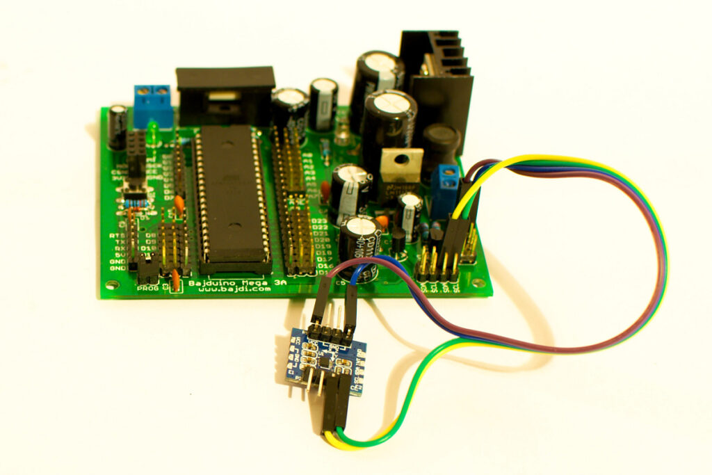
The MAG3110 uses the I2C bus to communicate with a micro controller. It works at voltages between 1.95 and 3.6V. The SDA and SCL lines must be between -0.3 and +0.3 of the input voltage according to the datasheet. I connected the sensor to my Bajduino Mega 3A board, it has an ATmega1284P-PU running at 5V and a logic level converter for the I2C bus. The logic level converter shifts the 5V I2C bus of the ATmega to 3.3V. Do not connect the sensor to a 5V Arduino I2C bus, it might work but for how long is another question.
After receiving the sensor I started searching for an Arduino library. Unfortunately I could not find one. The only thing I did find was an example sketch to get the raw readings of the sensor on the sparkfun website. I copied the sketch and tried to compile it. The compiler did not like it, it gave a bunch of errors that I had seen before. The sketch is a couple of years old and has not been updated for the revised Arduino Wire (I2C) library. Since Arduino 1.0 some changes were made to the Wire library so the sketch was not compatible any more. I quickly made some changes to make it work with the latest Arduino IDE. I’m using Arduino 1.0.3.
You can download the sketch here: MAG3110 sketch
The above sketch is useful to check if your sensor works but it will not give you a compass heading. The sketch only prints the raw values of the sensor. To calculate the heading you first need to calibrate the sensor. This is done by determining the sensor offsets for every axis. The sensor offsets must be sent to the sensor over the I2C bus. After this is done the sensor will take the offset values in to account. Then we can read from the sensor and calculate the heading using the scale factors (which are calculated from the offsets).
My goal was to write a sketch to do this using the Arduino Wire library but so far I have not succeeded in doing that 🙁
After browsing lots of web pages I found an Arduino sketch to calibrate the MAG3110 and determine the heading on this blog. One problem, the sketch does not use the Arduino Wire library, the person who made the sketch has written his own I2C Arduino library. Hats off 🙂
You can download the library here: http://users.soe.ucsc.edu/~karplus/Arduino/libraries/i2c/
The sketch I found also included code for an accelerometer. I copied the sketch and deleted all the code for the accelerometer. I was then able to calibrate the sensor and calculate the heading. Woohoo 🙂
You can download the sketch here: MAG3110 calibration.
I then wrote a simpler sketch that uses the offsets which I measured during the calibrating and calculates the heading.
So now I have a working piece of compass code which I can use in my robot sketches 🙂 I will take another shot at rewriting the sketch with the Arduino Wire library at a later time.
Here is the sketch:
// http://www.bajdi.com
// MAG3110 Compass sketch
// Used code found here: http://users.soe.ucsc.edu/~karplus/Arduino/accel_magnet/
// This sketch will print the heading calculated from the readings of a MAG3110 sensor

#include <i2c.h> // Use I2C library found here: http://users.soe.ucsc.edu/~karplus/Arduino/libraries/i2c/

#define degrees_per_radian  (180./3.14159265358979)

// minimum and maximum values seen during calibration time
int16_t mag_low_x = 2411;
int16_t mag_high_x = 3254;
int16_t mag_low_y = -3201;
int16_t mag_high_y = -2227;
int16_t mag_low_z = -581;
int16_t mag_high_z = 189;

// I2C 7-bit address of the magnetometer
#define MAG_3110_I2C  0x0E

// registers on the magnetometer
#define MAG_3110_DR_STATUS 0x00

// add 1 for LSB
#define MAG_3110_OUT_X_MSB 0x01
#define MAG_3110_OUT_Y_MSB 0x03
#define MAG_3110_OUT_Z_MSB 0x05

// add 1 for LSB  // user offset
#define MAG_3110_OFF_X_MSB 0x09
#define MAG_3110_OFF_Y_MSB 0x0B
#define MAG_3110_OFF_Z_MSB 0x0D

#define MAG_3110_CTRL_REG1 0x10
#define MAG_3110_CTRL_REG2 0x11

// Fields in registers
// CTRL_REG1: dr2,dr1,dr0  os1,os0  fr tm ac

// Sampling rate 80Hz
#define MAG_3110_SAMPLE80 0

// How many samples to average (lowers data rate)
#define MAG_3110_OVERSAMPLE1 0
#define MAG_3110_OVERSAMPLE2 0x08
#define MAG_3110_OVERSAMPLE3 0x10
#define MAG_3110_OVERSAMPLE4 0x18

// put in active mode
#define MAG_3110_ACTIVE 0x01

// CTRL_REG2: AUTO_MRST_EN  _ RAW MAG_RST _ _ _ _ _
// reset sensor after each reading
#define MAG_3110_AUTO_MRST_EN 0x80

// DR_STATUS Register ZYXOW ZOW YOW XOW ZYXDR ZDR YDR XDR
#define MAG_3110_ZYXDR	0x08

#define mag_write_reg(r,v)   (i2cWriteRegister(MAG_3110_I2C,r,v))
#define mag_read_reg(r)      (i2cReadRegister(MAG_3110_I2C,r))

inline uint8_t mag_data_ready(void)
{   return mag_read_reg(MAG_3110_DR_STATUS) & MAG_3110_ZYXDR;
}

void mag_read_xyz(int16_t&x, int16_t&y, int16_t&z)
{
    while (!mag_data_ready()) {} // wait for new set of data

    static uint8_t data[6];
    i2cReadRegisters(MAG_3110_I2C, MAG_3110_OUT_X_MSB, 6, data);
    x = (data[0]<<8) + data[1];
    y = (data[2]<<8) + data[3];
    z = (data[4]<<8) + data[5];
}

void mag_set_offsets(void)
{
    int16_t mag_x_offset = (mag_low_x+mag_high_x)/2;
    int16_t mag_y_offset = (mag_low_y+mag_high_y)/2;
    int16_t mag_z_offset = (mag_low_z+mag_high_z)/2;
    static uint8_t data[6];

    data[0]=mag_x_offset>>7;    data[1]=(mag_x_offset<<1)& 0xFF;
    data[2]=mag_y_offset>>7;    data[3]=(mag_y_offset<<1)& 0xFF;
    data[4]=mag_z_offset>>7;    data[5]=(mag_z_offset<<1)& 0xFF;

    i2cWriteRegisters(MAG_3110_I2C, MAG_3110_OFF_X_MSB, 6, data);
}

void print_heading(int16_t x, int16_t y, int16_t z)
{
  float mag_x_scale = 1.0/(mag_high_x-mag_low_x);
  float mag_y_scale = 1.0/(mag_high_y-mag_low_y);


  float heading = atan2(-y*mag_y_scale,x*mag_x_scale);
  if(heading < 0)
  {
  heading += 2*PI;  // correct for when the heading is negative
  }
  float headingDegrees = heading * degrees_per_radian;  // convert to degrees

        Serial.print("headingDegrees = " );
        Serial.print(headingDegrees);
        Serial.println();
}

void mag_setup(void)
{
    mag_write_reg(MAG_3110_CTRL_REG2, MAG_3110_AUTO_MRST_EN);
    mag_write_reg(MAG_3110_CTRL_REG1, MAG_3110_SAMPLE80+MAG_3110_OVERSAMPLE1+MAG_3110_ACTIVE);
    mag_set_offsets();
}

void setup(void)
{
    Serial.begin(115200);

    i2cInit();
    i2cSetBitrate(100);  // try 100kHz
    delay(20);
    mag_setup();
    delay(50);
}

void loop(void)
{
    int mag_x,mag_y,mag_z;
    mag_read_xyz(mag_x,mag_y,mag_z);  // read from sensor
    print_heading(mag_x,mag_y,mag_z);  // print the heading
}
Download it here: MAG3110 compass sketch
The sketch works but will only give an accurate heading when the sensor is level. For this reason magnetometers are used in combination with an accelerometer to measure the tilt angle and compensate the reading of the magnetometer. That way you can still get an accurate heading when the sensor is not level.
This is the second magnetometer that I have bought. I already own a board with 3 sensors including a HMC5883L magnetometer and a ADXL345 accelerometer. The HMC5883L is more popular in the Arduino community and cheaper. I have used the board on my Rover 5 and even made a video of it.
Hello, can I ask you what process did you follow to find the maximum and minimum offset values?
Have you tried my MAG3010 calibration sketch? Follow the instructions in the serial monitor and it should give you the offset values.
hello again!yes i did!the problem is that after calibration my sensor should detect the magnetic field of the earth(since i got it in open air environment) but the magnitude of the magnetic field it measures is approximately 20uT and it should be around 45uT!
for example when i apply the calibration code with z vertical to the desk and rotating around z i get x_off = -2517 , y_pff = 1869 z_pff = -270 which is totally different from what you get as offset values and i am a bit confused :S
Different chip, different environment? I wrote that sketch in Thailand. I then came back to Europe and mounted the sensor on a robot. I had to recalibrate the sensor and got very different offset results. So I wouldn’t worry that you get different results then mine.
yes you are right…but after calibration shouldn;t we get the magnetic field of our area!for me it should be around 45uT but the magnitude of the magnetic field sqrt(x^2+y^2+z^2) although is close to being constant,it has a value of 20uT!any tip onwhat could be wrong?i am stuck at it for around a week now and can not find something to fix it!thanx for your time 🙂
Hi,
Can you please help me in ADXL345 code as well. I have ADXL345 sensor and planning to use MAG3110 sensor with it as it is more cheaper than HMC5883L. But i am at first struggling with ADXL345 to get the correct reading. Also suggest if this combination will work for me. I am using STM32F207VC controller from ST microelectronics.
Also please suggest me which sensor would be good to go in terms of stability and accuracy out of HMC5883L and MAG3110.
Awaiting your reply eagerly.
Best Regards
Hem
Here you can find a comparison between different magnetometers: http://www.pitlab.com/autopitlot-articles/54-comparision-of-magnetometers.html
Thanks a lot for the link.
Can you please help me in working aof ADXL345 for data flow.
I am giving a CLOCK out of 16MHz from my controller with prescaler of 32 for SCLK.
Please help and suggest me or provide the working flow if available.
Also integration of ADXL345 and MAG3110
Best Regards
Hem
Sorry but you are asking the wrong person for help… I now very little about programming. I can program some things with Arduino but that’s about it 🙂
Hello, me and two friends are doing a school project where we want to have a compass on an object. We have a MAG 3110 and an accelerometer and we are able to run your sketch but we aren’t quite sure of what the sketch does. Could you maybe explain it to me? And is it possible to fix the direction to another direction?
Thank you.
Read the posts about the MAG3110 on this blog: http://gasstationwithoutpumps.wordpress.com/?s=mag3110
I get an error saying i2cReadRegister was not declared in this scope. I have included the i2c library and all.
Okay, it only prints the heading once and then prints gibberish and then wont work again. Just sometimes. Do you know why?
My crystal ball is broken 🙂
How is your MAG3110 connected to your Arduino? Are you using a logic level converter to convert the Arduino 5V I2C to 3V3? Which pullup resistors are you using on the I2C bus? Have you checked the I2C bus with an oscilloscope or logic analyzer?
Marcus’ “I get an error saying i2cReadRegister was not declared in this scope. ”
The line:
#include
indicates a library and so it looks for the file with the libraries.
Change it to:
#include “i2c.h”
and it should work, at least it did for me.
how i should give addresses for my i2c interfaced with my magnetometer…
Actually i am making the project of pipeline inspection guage for which I had to use MAG3110,HMC5883L using arduino mega 2560….I am unable to acquire the data from each of them individually.I need to know the procedure for acquiring the data from these sensors using the concept of i2c pins.